- Home
- :
- All Communities
- :
- Products
- :
- Geoprocessing
- :
- Geoprocessing Questions
- :
- using coordinate priority in create route
- Subscribe to RSS Feed
- Mark Topic as New
- Mark Topic as Read
- Float this Topic for Current User
- Bookmark
- Subscribe
- Mute
- Printer Friendly Page
- Mark as New
- Bookmark
- Subscribe
- Mute
- Subscribe to RSS Feed
- Permalink
How to find the minimum bounding rectangles (MBR) of the route in order to calculate the shortest distance to the MBR to determine the direction of measurement? because inconsistency problems often occur in measurement direction.
Solved! Go to Solution.
Accepted Solutions
- Mark as New
- Bookmark
- Subscribe
- Mute
- Subscribe to RSS Feed
- Permalink
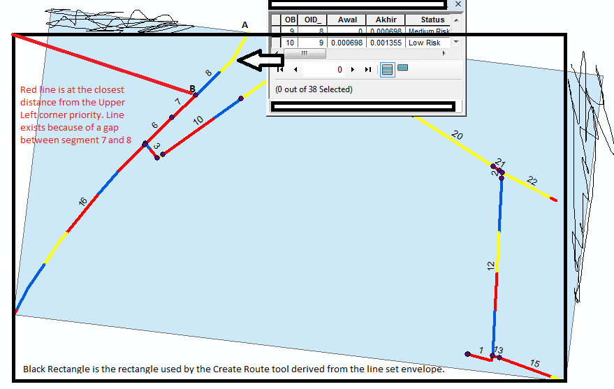
Below is the picture you need to see that represents what the Create Route tool actually does. The actual behavior is different from what you have been imagining that it is doing. No tool does what you were imagining, because a Rectangle By Width is a time consuming rectangle to create and no tool uses it by default. As far as I know, other than the Minimum Bounding Geometry tool when the Rectangle By Width or Rectangle by Area option is chosen. all rectangles evaluated within the tools of ArcGIS are based on envelopes. Only custom user defined tools will actually use the Rectangle By Width shape to do further geoprocessing.
When I stated that I use the Rectangle By Width to evaluate routes, that meant I use it in my custom tools only. That statement was also made before I knew what your network looked like and I thought you might be dealing with a road network, like I do, where routes are simple with no branches and the lines making up a route are for the most part all oriented in a single direction with relatively few gaps between lines. My network is much more of an ideal input for using the Create Route tool with the Coordinate Priority option and the Rectangle By Width Minimum Bounding Geometry for creating and evaluating route measures than the network you are inputting to either of those tools. In my network no acceptable route that I create would ever come close to the level of complexity of the route shown in your picture. Virtually no tool Esri publishes is designed to deal with the level of complexity shown in your picture nearly as well as they are designed to deal with the simplest geometry cases.
- Mark as New
- Bookmark
- Subscribe
- Mute
- Subscribe to RSS Feed
- Permalink
It is not really clear what problem you are trying to solve. Is it a problem of measure directions changing within a single route due to bad line topology and contradictory orientations of the input lines relative to the coordinate priority you chose? Or is this a problem of inconsistent directions between multiple routes that you want to control better so that you can predict the compass direction of the increasing measures of each route?
The Minimum Bounding Geometry tool can be applied to the routes to find out some aspects or overall route orientation, but it is not the entire solution. I do use this tool with the Rectangle by Width option to get the overall sense of the orientation of my routes. But it only really works if the route was built correctly to begin with.
I find that knowing the number of line parts that make up a route is the most important information, since single part routes are consistent within themselves. Single part routes only cause issues between itself and other routes for orientation issues and for them knowing the Minimum Bounding Rectangle is useful.
Routes that have internally inconsistent measures mess this up and only can apply to the routes that are made up of multiple line parts. So calculating a PARTS field is important. The Python field calculation for that field is:
!Shape.partCount!
The other field that is important for finding and fixing routes with internal measure problems due to branching or looping is MMONOTONIC, which tells if measures continually increase or if they are internally inconsistent within a single route. This value is also reported by the Identify Measure tool, but having it in a field is more useful for analyzing your whole route network than trying to use that tool one route at a time. The MMonotonicy values and their domain translations are:
1 = Strictly Increasing
2 = All Measures are Level
3 = Increasing with Levels
4 = Strictly Decreasing
5 = Increasing and Decreasing
6 = Decreasing with Levels
7 = Increasing and Decreasing with Levels
8 = All Measures are NaN
9 = Increasing with NaN
10 = Measures with Levels and NaN only
11 = Increasing with Levels and Nan
12 = Decreasing with NaN
13 = Increasing and Decreasing with NaN
14 = Decreasing with Levels and NaN
15 = Increasing and Decreasing with Levels and NaN
This field can be calculated with the field calculator with this Python calculation:
Parser: Python
Show Codeblock: Checked
Pre-Logic Script Code:
def MMonotonicity(feat):
 partnum = 0

 # Count the number of points in the current multipart feature
 partcount = feat.partCount
 pntcount = 0
 mmonotonicity = 0
 lastM = -100000000

 # Enter while loop for each part in the feature (if a singlepart feature
 # this will occur only once)
 #
 while partnum < partcount:
  part = feat.getPart(partnum)
  pnt = part.next()

  # Enter while loop for each vertex
  #
  while pnt:
   pntcount += 1
   if lastM < pnt.M and lastM != -100000000:
    mmonotonicity = mmonotonicity | 1
   if lastM == pnt.M and lastM != -100000000:
    mmonotonicity = mmonotonicity | 2
   if lastM > pnt.M and lastM != -100000000:
    mmonotonicity = mmonotonicity | 4
   if not pnt.M:
    mmonotonicity = mmonotonicity | 8
   lastM = pnt.M
   pnt = part.next()

   # If pnt is null, either the part is finished or there is an
   # interior ring
   #
   if not pnt:
    pnt = part.next()
  partnum += 1
 return mmonotonicity
Expression: MMonotonicity( !Shape!)
- Mark as New
- Bookmark
- Subscribe
- Mute
- Subscribe to RSS Feed
- Permalink
After using minimum bounding geometry tool, I still have problem like in the picture. the problem in line with label 8, medium risk in yellow line with from and to measure 0 - 0.000698 and low risk in blue line. According coordinate priority upper left that measures will be accumulated from the point closest to the minimum bounding rectangle upper left corner, the result segmented color is from A to B but the result should is from B to A.
I don't have idea why that happen?
- Mark as New
- Bookmark
- Subscribe
- Mute
- Subscribe to RSS Feed
- Permalink
I don't know what your lines represent, but I know why the tool did what it did. Position B is closest to the Minimum Bounding Rectangle upper left corner that is built with the Envelope Option, not by the Rectangle By Area or Rectangle By Width option. The Create Route tool does not use a sophisticated rectangle like you have shown, it uses the simple Envelope rectangle for speed. If you want to figure out what the tool will do, the Envelope Rectangle is the rectangle you have to examine. Additionally, there must be a nearly invisible gap between the two original lines that are supposed to meet at position B. You need topology to find and fix the huge number gaps your network will have if you did not use topology. Topology would show you that you have two dangles at position B. It is impossible to do correct snapping in a network without it in my opinion, because you will never see with your eyes all of the unwanted tiny gaps the Create Route tool sees. Your coordinate priority is also perpedicular to the route, which is bad. You should always use a corner that is more or less parallel with your route (in this case only lower left or lower right are the only predictable route start coordinates with the entire set of lines in the rectangle)
Larger gaps can be allowed, but they have to be in line with the best position of the Coordinate Priority and the two closest lines cannot overshoot each other. If the line the Create Route tool is currently assigning measures to goes further lower right than the end of the closest line, it will begin measuring from the far end of that new line at its lower right corner and come back up toward the upper left. If on the other hand the closest point of the new line is further lower right than the end of the line currently being assigned measures then the gap is fine.
If all the lines in the rectangle form one route you will never get a fully sensible set of measures using the Create Route tool with the Coordinate Priority option. You have branches, which means the route is not simple. My MMonotonicity calculation would show that the route is complex, because it would not have a value of 1 (Continuously increasing measures). Once line sets are complex the Create Route tool does many more steps than simply find the perfect start position and apply measures in ways that you will want. I would say that you would have to break these lines into about 5 separate simple routes to get sensible measures (The lines in alignment with each other between segment 8 and 16 would be one route and that route should be built from the upper right or lower left, because perpendicular coordinate priorities line upper left and lower right will have bad results. The line segment 3 by itself because of its branching with segments 6 and 16 and its gap and change in alignment relative to segment 10. Maybe segments 10 through 22, if no gaps occur under your table view and you use the Lower Left coordinate priority, not upper left. Segments 2 and 12. Segments 1, 13 and 15, because the gap is in line with each segment alignment and the coordinate priority). However, that is only a guess, because I would need to know what these lines represent and why they are assigned the same route ID to understand how to simplify them
I assign a field with a coordinate priority value to my original lines and make sure my routes have the same internal coordinate priority, but adjoining routes may get a different coordinate priority to ensure the first line I want to start the route is the beginning line. I select each coordinate priority field value in separate sets, build the routes using separate Create Route tool runs, and then append them together.
Road networks on a grid lend themselves to coordinate priority route creation, but other route networks types may not. River networks often have to use the Field Measure methods to build the measures in the correct orientation and line order, since branching is expected and complex routes have to be allowed.
In any case, the Create Route tool makes no attempt to do complex analysis of a set of lines once they fail to comply with the few simple rules the tool attempts to apply. It just continues to enforce the simple rules it was instructed to do on the complex line set, and complex gaps and branches in a set of lines using these simple rules will result in measures that will not make sense to a human observer.
- Mark as New
- Bookmark
- Subscribe
- Mute
- Subscribe to RSS Feed
- Permalink

The line represents a simulation pipeline with vulnerability. In this case, I use linear referencing ArcGIS. The pipeline became input in create route tools with coordinate priority parameter upper left. Next step, I use make route event layer tools with 2 input, pipeline from output create route tools and table event vulnerability.
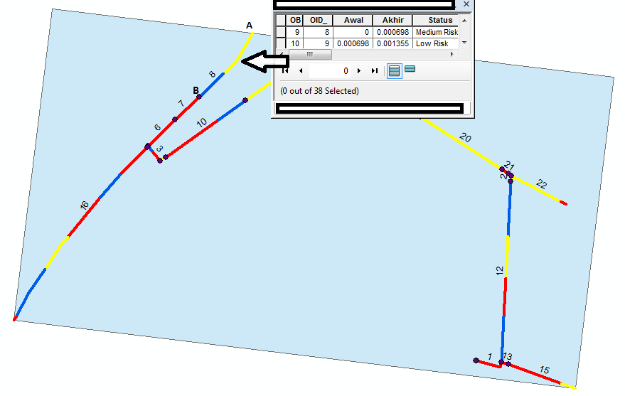
The direction of result is in line 8 from A to B, line 6 from D to C, line 16 from D to E, line 10 from F to G, and line 12 from H to I. If using Minimum Bounding Rectangle by Width option or envelope option so the result should is in line 8 from B to A because B closer than A to upper left corner. As well with line 6 from D to C, the result should from C to D because C closer than D to upper left corner too. But, the other line appropriate with principle coordinate priority upper left that measures will be accumulated from the point closest to the minimum bounding rectangle upper left corner. I confused how to work with coordinate priority upper left.
- Mark as New
- Bookmark
- Subscribe
- Mute
- Subscribe to RSS Feed
- Permalink
The rectangle is not the Rectangle by Width in the Create Route tool, so your rectangle shown is not representative of what the tool used. The Rectangle by Envelope is used and its upper left corner shifts enough southwesterly that coordinate B is the closest point on the set of lines, And because point B has a gap between segment 7 and 8, it is the beginning of the route. If segments 7 and 8 had no gap between them, then point A would have been used for the start.
Also points A through E are more perpendicular to the Coordinate priority than they are parallel. All lines that are perpendicular to a coordinate priority start in the middle of the set of lines if there is even the smallest gap between them. Coordinate Priority Upper left is only predictable for lines that have their beginning point oriented between due west and due north. The point you want to begin this line is oriented between due north and due east, which makes is a perpendicular line to the coordinate priority of upper left, so the tool favors the middle of the line over the ends if it finds any gap in the line set.
This has proven true for thousands of routes I have created with the Create Route tool every weekend for years. You must use topology to truly get rid of all gaps the tool can see that you cannot see. The tool's behavior for Upper Left priority is consistently going to go to start at the middle of any set of lines that is oriented from northeast to southwest if a gap exists anywhere in the middle of the line set.
- Mark as New
- Bookmark
- Subscribe
- Mute
- Subscribe to RSS Feed
- Permalink
Below is the picture you need to see that represents what the Create Route tool actually does. The actual behavior is different from what you have been imagining that it is doing. No tool does what you were imagining, because a Rectangle By Width is a time consuming rectangle to create and no tool uses it by default. As far as I know, other than the Minimum Bounding Geometry tool when the Rectangle By Width or Rectangle by Area option is chosen. all rectangles evaluated within the tools of ArcGIS are based on envelopes. Only custom user defined tools will actually use the Rectangle By Width shape to do further geoprocessing.
When I stated that I use the Rectangle By Width to evaluate routes, that meant I use it in my custom tools only. That statement was also made before I knew what your network looked like and I thought you might be dealing with a road network, like I do, where routes are simple with no branches and the lines making up a route are for the most part all oriented in a single direction with relatively few gaps between lines. My network is much more of an ideal input for using the Create Route tool with the Coordinate Priority option and the Rectangle By Width Minimum Bounding Geometry for creating and evaluating route measures than the network you are inputting to either of those tools. In my network no acceptable route that I create would ever come close to the level of complexity of the route shown in your picture. Virtually no tool Esri publishes is designed to deal with the level of complexity shown in your picture nearly as well as they are designed to deal with the simplest geometry cases.