Turn on suggestions
Auto-suggest helps you quickly narrow down your search results by suggesting possible matches as you type.
Cancel
- Home
- :
- All Communities
- :
- Products
- :
- Geoprocessing
- :
- Geoprocessing Questions
- :
- Geocoding signs based on buffer analysis
Options
- Subscribe to RSS Feed
- Mark Topic as New
- Mark Topic as Read
- Float this Topic for Current User
- Bookmark
- Subscribe
- Mute
- Printer Friendly Page
Geocoding signs based on buffer analysis
Subscribe
2025
1
07-02-2013 05:33 AM
07-02-2013
05:33 AM
- Mark as New
- Bookmark
- Subscribe
- Mute
- Subscribe to RSS Feed
- Permalink
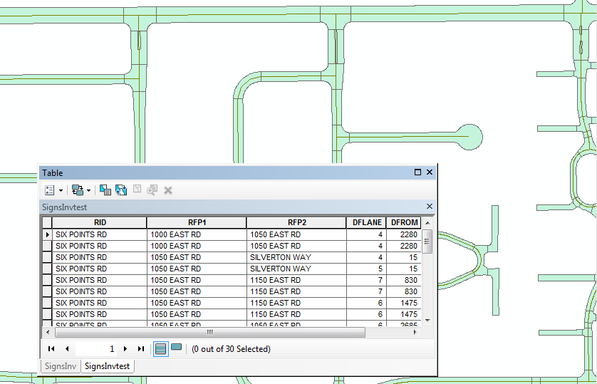
I have a database of 22,000+ signs that contains the offset from centerline along with a distance to/from the edge of pavement to a specific intersecting road for each sign. I also have a street centerline layer and pavement polygon layer with edge of pavements. I'm trying to create point features for the signs based on the offset from centerline and the distance from the nearest intersecting roadway. Looking for some ideas on what tools to use for this analysis (buffer, selectlayerbylocation, etc?)
[ATTACH=CONFIG]25644[/ATTACH]
[ATTACH=CONFIG]25644[/ATTACH]
1 Reply
07-02-2013
07:06 AM
- Mark as New
- Bookmark
- Subscribe
- Mute
- Subscribe to RSS Feed
- Permalink
I have a database of 22,000+ signs that contains the offset from centerline along with a distance to/from the edge of pavement to a specific intersecting road for each sign. I also have a street centerline layer and pavement polygon layer with edge of pavements. I'm trying to create point features for the signs based on the offset from centerline and the distance from the nearest intersecting roadway. Looking for some ideas on what tools to use for this analysis (buffer, selectlayerbylocation, etc?)
[ATTACH=CONFIG]25644[/ATTACH]
This is something I do every day using Linear Referencing. The basics of Linear Referencing is that you would derive a Route feature class from your Centerlines based on each street name and combine all related lines into a single feature. Each Route feature has a unique identifier known as a RouteID or RID, which can be either a number or a string (typically based on the road name, but made unigue in some way if two road features are named the same in different parts of your jurisdiction). This road feature stores a Polyline M feature type. The M stands for measure and is added to the polyline feature in addition to the X and Y coordinates stored as part of the shape. Measures for your type of problem are based on the length of the road and are typically stored as feet or miles in the US or meters or kilometers elsewhere in the world typically matching the units of offset reported in your data. When a separate table stores a RID value and one or two measure values that fits within the length of the road, that table can be made into a Linear Referncing event table. With one measure value you can create a point along your Route centerline at the measure location (like for a sign), and with two measures you can create a line segment along your Route centerline (like for pavement management segments).
To solve your problem you also need a set of intersection points derived from your Centerlines. I have a point feature class with one unique point at each intersection storing the street names concatenated together in alphabetical order. I derive from that a table of every unique street name pair combination in every order concatenated together at each intersection that stores the associated RouteIDs and measure value of the first street name of the pair for that intersection location. By using joins of concatenated pairs of street names from my input data I can transfer to my sign events the fixed position of the intersection based on the linear referencing RouteID and measure.
To deal with the offset along the road it is just a matter of either adding or subtracting the offset distance of your sign from the intersection. I store a field that contains a 1 or a -1 as a multiplier that translates north/south or east/west into the appropriately signed value. Typically for road systems in the US measures should increase from south to north or from west to east. As a result, typically south and west offsets equal -1 and north and east offsets equal 1. To get the actual measure of the location of the sign along the road the formula is then:
Intersection_measure + Direction_Multiplier * Offset_Distance
Once the Routes and intersection tables are created, the procedure to locate your signs goes as follows. Calculate a concatenated street name pair in the sign event table as a join field. You then join them to the table of intersection pair names with RouteIDs and measures of the intersections and use the field calculator to transfer the fixed intersection RouteID and Intersection_Measure to the events. You can manually finish this step for thousands of signs in just a few minutes. Break the join. Then in a Direction_Mulitplier field on your sign event you calculate a -1 for south and west offset signs and a 1 for north and east offset signs using two separate selections and calculations. Now in a field holding the actual measure of the sign do the above calculation. Make the sign table into a Linear Referencing Event table and all of your signs will now be located along the centerline at the described locations.
Additionally, Linear Referencing supports side offsets as well. Similar to offsets along roadways, determining whether a point or line segment offsets to the right or the left of the line is represented by a positive or negative side distance offset value. So I have a Side_Multiplier that contains a 1 or -1. The determination of whether the side mulitplier is positive or negative is dependent on the direction of travel faced by the sign.
In a perfect world the actual geolocating operation can be finished in under 15 minutes using my set up if all of the inputs fit my assumptions. Unfortunately this is far from a perfect world. Faulty input data or disconnects between reported field conditions and your centerline network result in false or failed matches that have to be examined and corrected. For example, roads that curve back on themselves can reverse everything about the way field conditions are reported. Fortunately Linear Referencing supports an angle field that can be generated for the intersection locations which can be used to detect and select for reversed or ambiguous road orientation issues. I have a set of SQL statements that let me find and fix these issues using angle field ranges that do not normally fit the reported direction or my assumptions.
The time consuming aspect of this process is the same as any other geocoding operation. The most common problem is that field workers do not use standard street name suffix values or correct suffix values. RD and DR are reversed as much as 40% of the time. Silent letters and double/single letter spellings or spellings with spaces or no spaces between name parts cause issues, etc. The Street Name pair table has fields for the street names separately for this reason so I can do validation using Like statements to find close but not exact pairs. Other geocoding techniques can be used to match your network to your reported field data as well.
This post is long because it took me a long time to figure this all out on my own. Almost no help exists to set this up correctly and is only recently getting some support from ESRI. I have only scratched the surface of what I have scripted and automated to get this set up, but I am willing to help and can point you to other posts where I have offered this help. My sign database is 45,000+ signs. I use this technique with Pavement Management, collisions, traffic signals, sidewalks, curb ramps, road improvement projects, etc. basically it can be used for every aspect of street inventory.