Turn on suggestions
Auto-suggest helps you quickly narrow down your search results by suggesting possible matches as you type.
Cancel
- Home
- :
- All Communities
- :
- Products
- :
- Geoprocessing
- :
- Geoprocessing Questions
- :
- Re: Conversion from .kml, global orbits: Arc not t...
Options
- Subscribe to RSS Feed
- Mark Topic as New
- Mark Topic as Read
- Float this Topic for Current User
- Bookmark
- Subscribe
- Mute
- Printer Friendly Page
Conversion from .kml, global orbits: Arc not treating polar orbiting paths correctly
Subscribe
8893
12
04-07-2014 03:28 PM
04-07-2014
03:28 PM
- Mark as New
- Bookmark
- Subscribe
- Mute
- Subscribe to RSS Feed
- Permalink
Hi all,
Not sure if this is the correct forum for this question/problem, but I couldn't find a strictly projecting category.
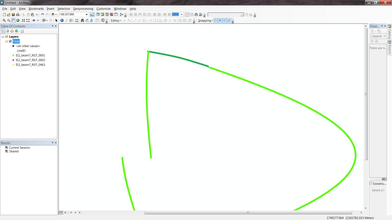
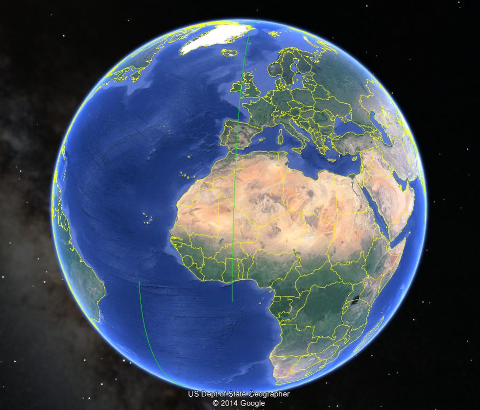
Anyways, I have a few thousand KML files that each have a single polyline, each representing a single satellite orbital path. I am putting them through a script that converts to each file to layer and appends them to one giant gdb, then projects the gdb into Sinusoidal. I'm not quite sure if this is occurring with the conversion to layer/gdb or the projecting (I think it's the conversion), but when it comes time for the orbit to circle around the North pole, it seems that ESRI doesn't know what to do. I've attached a screenshot of what one of the orbits actually looks like, both unprojected (1st image) and in sinusoidal (2nd image), and an edited version of the sinusoidal orbit, according to the way I think it is supposed to look like (3rd image). Additionally, I've attached a screenshot of what the same orbit looks like as it goes around the pole in Google Earth (4th image), since that's the only place I can view KMLs it seems.
Does anyone have any suggestions on how to get around this issue? I need these to be accurate to do some analysis on the paths of the orbits, and the incorrect conversion is going to interfere with that badly. To do the analysis I have to work with shapefiles or geodatabases because there's not much I can do with just the kml in terms of what I need to get done. Manually editing is out of the question as there are thousands of polylines.
Any comments/suggestions/resources would be very helpful.
Thanks a lot
[ATTACH=CONFIG]32892[/ATTACH]
[ATTACH=CONFIG]32893[/ATTACH]
[ATTACH=CONFIG]32894[/ATTACH]
[ATTACH=CONFIG]32895[/ATTACH]
*EDIT: I changed the title to reflect updated problem. Looking at the 1st image, I'm pretty sure the problem is with the conversion and not the projection.
Not sure if this is the correct forum for this question/problem, but I couldn't find a strictly projecting category.
Anyways, I have a few thousand KML files that each have a single polyline, each representing a single satellite orbital path. I am putting them through a script that converts to each file to layer and appends them to one giant gdb, then projects the gdb into Sinusoidal. I'm not quite sure if this is occurring with the conversion to layer/gdb or the projecting (I think it's the conversion), but when it comes time for the orbit to circle around the North pole, it seems that ESRI doesn't know what to do. I've attached a screenshot of what one of the orbits actually looks like, both unprojected (1st image) and in sinusoidal (2nd image), and an edited version of the sinusoidal orbit, according to the way I think it is supposed to look like (3rd image). Additionally, I've attached a screenshot of what the same orbit looks like as it goes around the pole in Google Earth (4th image), since that's the only place I can view KMLs it seems.
Does anyone have any suggestions on how to get around this issue? I need these to be accurate to do some analysis on the paths of the orbits, and the incorrect conversion is going to interfere with that badly. To do the analysis I have to work with shapefiles or geodatabases because there's not much I can do with just the kml in terms of what I need to get done. Manually editing is out of the question as there are thousands of polylines.
Any comments/suggestions/resources would be very helpful.
Thanks a lot
[ATTACH=CONFIG]32892[/ATTACH]
[ATTACH=CONFIG]32893[/ATTACH]
[ATTACH=CONFIG]32894[/ATTACH]
[ATTACH=CONFIG]32895[/ATTACH]
*EDIT: I changed the title to reflect updated problem. Looking at the 1st image, I'm pretty sure the problem is with the conversion and not the projection.
12 Replies
04-07-2014
03:56 PM
- Mark as New
- Bookmark
- Subscribe
- Mute
- Subscribe to RSS Feed
- Permalink
The first thing I'd try is the Densify tool to add coordinates to your original dataset (before projecting to Sinusoidal). I think what might be happening is that you have long line segments without intermediate shapepoints. When projecting, the line endpoints are projected, but the space in between isn't. Anyway, try that first. Maybe start with 10km distance and see what happens. If it looks like it will solve the issue, you can decrease the distance for finer resolution. If this isn't the issue, I'll investigate further.
by
Anonymous User
Not applicable
04-07-2014
04:12 PM
- Mark as New
- Bookmark
- Subscribe
- Mute
- Subscribe to RSS Feed
- Permalink
Original User: mwooten3
Dale,
Thanks for getting back to me. I will try the densify thing tomorrow at work, but the more I look, the more I think the problem is not with the way ESRI is projecting the data, but with the way it is converting from KML. If you look at the first image (converted but unprojected orbit line), you see the line across the top that connects where the orbit is crossing over the 180th meridian. I believe that when looking at the unprojected orbit (which is in GCS_84 coordinate system, which I think is the default of the KML to layer tool), it should look disconnected as the orbit crosses a longitude of 180 degrees, even though in reality it is connected as it passes through 180 degrees longitude. Does this make sense?
If this is the case, I'm really at a loss. The very first thing I need to do in a long list of steps is convert to gdb, so if I can't do that I don't really know what I'll do. Any ideas?
Thanks!
The first thing I'd try is the Densify tool to add coordinates to your original dataset (before projecting to Sinusoidal). I think what might be happening is that you have long line segments without intermediate shapepoints. When projecting, the line endpoints are projected, but the space in between isn't. Anyway, try that first. Maybe start with 10km distance and see what happens. If it looks like it will solve the issue, you can decrease the distance for finer resolution. If this isn't the issue, I'll investigate further.
Dale,
Thanks for getting back to me. I will try the densify thing tomorrow at work, but the more I look, the more I think the problem is not with the way ESRI is projecting the data, but with the way it is converting from KML. If you look at the first image (converted but unprojected orbit line), you see the line across the top that connects where the orbit is crossing over the 180th meridian. I believe that when looking at the unprojected orbit (which is in GCS_84 coordinate system, which I think is the default of the KML to layer tool), it should look disconnected as the orbit crosses a longitude of 180 degrees, even though in reality it is connected as it passes through 180 degrees longitude. Does this make sense?
If this is the case, I'm really at a loss. The very first thing I need to do in a long list of steps is convert to gdb, so if I can't do that I don't really know what I'll do. Any ideas?
Thanks!
04-09-2014
05:00 AM
- Mark as New
- Bookmark
- Subscribe
- Mute
- Subscribe to RSS Feed
- Permalink
Which version of ArcMap?
Can you share one of your KML files for me to try?
Can you share one of your KML files for me to try?
by
Anonymous User
Not applicable
04-09-2014
06:24 AM
- Mark as New
- Bookmark
- Subscribe
- Mute
- Subscribe to RSS Feed
- Permalink
Original User: mwooten3
Hi Kevin,
I'm using Arc 10.2.1. The forum won't let me attach the KML. How can I get you the file?
Thanks!
Which version of ArcMap?
Can you share one of your KML files for me to try?
Hi Kevin,
I'm using Arc 10.2.1. The forum won't let me attach the KML. How can I get you the file?
Thanks!
04-09-2014
09:38 AM
- Mark as New
- Bookmark
- Subscribe
- Mute
- Subscribe to RSS Feed
- Permalink
I don't see your image 2 as problematic:
it looks like a reasonable representation of the line in image 1
and in Google Earth
You likely want to split your track wherever it crosses the 180° meridian,
so Arc will not wrap the line back across the whole earth to continue the single feature.
We know that the world is continuous across that meridian,
and thus the feature should break there when projected,
but the feature coordinate stream tells Arc that the line goes from hither to yon,
and the only way Arc knows to get from hither to yon
is right across the face of the flattened earth.
Yes, Arc is making some unfounded assumptions about how the line should run,
but your 'edited' version is only a reflection of your own unfounded assumptions about how the line should run.
Split the line, and see if you two can come to some sort of agreement.
by
Anonymous User
Not applicable
04-09-2014
10:20 AM
- Mark as New
- Bookmark
- Subscribe
- Mute
- Subscribe to RSS Feed
- Permalink
Original User: mwooten3
It's problematic because of what I need to do with the lines. I need the line to represent the actual path of the satellite because the analysis depends on the actual path. It's not reasonable because the satellite does not actually follow the line that Arc is showing, making it an inaccurate representation of the orbit. A satellite orbits the Earth, and takes measurements in accordance with the path of the orbit. The extra line indicates there are measurements being taken along that line, when in reality there are no such measurements. My analysis is looking at the measurements, which are taken every 1000m along the orbital paths, and therefore I cannot use a representation of measurements that are not actually there.
There are no assumptions being made in the edit, besides the fact that I may be a little off on the exact location of the orbit, but it is generally the path the orbit takes. You can see this by looking at the same orbit in Google Earth.
I understand why Arc is doing what it's doing. It makes sense that it wants to draw a line to make the line appear to be one feature, even though we know the line is already connected, just passing the 180deg. longitude. Unfortunately, that doesn't make my problem go away.
Anything that involves manually editing will not work, as I have hundreds of thousands of orbit lines to process. If I split the lines into two features, the spacing of the measurements wouldn't be accurate, as when moving to the second part of the line, the measurement of every 1000m would restart. I have considered this approach, but there is a lot of uncertainty in it.
Basically, I need to somehow convert these orbit lines into points spaced at every 1000m along the line. I have everything scripted, only some of the points created (the ones along the fake line) are inaccurate due to the conversion, messing up the entire analysis. I've thought about taking the coordinates of the lines (which are spaced at 700m) from the kml file and using them directly to find the coordinates of points spaced every 1000m, and then creating a point feature class from the coordinates. There must be a way to find these 1000m-spaced points using the distance b/w coordinate points (haversine formula I believe) and the direction towards the next point in the list, but I'm not sure I could actually implement it. I've spent a good amount of time preparing the other solution and writing the script, and it's unfortunate that the only thing standing in between me and the finish line is Arc's inability to interpret global .kml files.
I don't see your image 2 as problematic:
it looks like a reasonable representation of the line in image 1
and in Google Earth
You likely want to split your track wherever it crosses the 180° meridian,
so Arc will not wrap the line back across the whole earth to continue the single feature.
We know that the world is continuous across that meridian,
and thus the feature should break there when projected,
but the feature coordinate stream tells Arc that the line goes from hither to yon,
and the only way Arc knows to get from hither to yon
is right across the face of the flattened earth.
Yes, Arc is making some unfounded assumptions about how the line should run,
but your 'edited' version is only a reflection of your own unfounded assumptions about how the line should run.
Split the line, and see if you two can come to some sort of agreement.
It's problematic because of what I need to do with the lines. I need the line to represent the actual path of the satellite because the analysis depends on the actual path. It's not reasonable because the satellite does not actually follow the line that Arc is showing, making it an inaccurate representation of the orbit. A satellite orbits the Earth, and takes measurements in accordance with the path of the orbit. The extra line indicates there are measurements being taken along that line, when in reality there are no such measurements. My analysis is looking at the measurements, which are taken every 1000m along the orbital paths, and therefore I cannot use a representation of measurements that are not actually there.
There are no assumptions being made in the edit, besides the fact that I may be a little off on the exact location of the orbit, but it is generally the path the orbit takes. You can see this by looking at the same orbit in Google Earth.
I understand why Arc is doing what it's doing. It makes sense that it wants to draw a line to make the line appear to be one feature, even though we know the line is already connected, just passing the 180deg. longitude. Unfortunately, that doesn't make my problem go away.
Anything that involves manually editing will not work, as I have hundreds of thousands of orbit lines to process. If I split the lines into two features, the spacing of the measurements wouldn't be accurate, as when moving to the second part of the line, the measurement of every 1000m would restart. I have considered this approach, but there is a lot of uncertainty in it.
Basically, I need to somehow convert these orbit lines into points spaced at every 1000m along the line. I have everything scripted, only some of the points created (the ones along the fake line) are inaccurate due to the conversion, messing up the entire analysis. I've thought about taking the coordinates of the lines (which are spaced at 700m) from the kml file and using them directly to find the coordinates of points spaced every 1000m, and then creating a point feature class from the coordinates. There must be a way to find these 1000m-spaced points using the distance b/w coordinate points (haversine formula I believe) and the direction towards the next point in the list, but I'm not sure I could actually implement it. I've spent a good amount of time preparing the other solution and writing the script, and it's unfortunate that the only thing standing in between me and the finish line is Arc's inability to interpret global .kml files.
04-09-2014
10:54 AM
- Mark as New
- Bookmark
- Subscribe
- Mute
- Subscribe to RSS Feed
- Permalink
Just zip up a kml/kmz and you can attach the file to your post.
by
Anonymous User
Not applicable
04-09-2014
10:57 AM
- Mark as New
- Bookmark
- Subscribe
- Mute
- Subscribe to RSS Feed
- Permalink
04-10-2014
04:20 AM
- Mark as New
- Bookmark
- Subscribe
- Mute
- Subscribe to RSS Feed
- Permalink
Yes, I understand that you "need the line to represent the actual path of the satellite".
It is also quite clear that the imaginary part of the line is what you need to eliminate,
and that manual manipulation is not a viable option.
I am not quite so slow as all that.
If you break line where it crosses the meridian you will have three segments:
part 1 of the path
part 2 of the path
and the straight bit across the face of the map.
the straight part should have just two nodes and
the y values of the two ends will be equal and
the x of one end will be at -180 and the other at 180
That should be enough to pick the bad one out of the three automatically.
There are also options for automatically breaking up the original line.
I leave this as a exercise for the student.
I referred to your mistaken assumptions in that your sketch 'corrected' the path
by joining it down the wrong side of the sinusodial shape.
Your 'correction' did not, in fact correct anything: it simply moved the path.
In fact, that path had to start off to the left and then reappear on the right,
not just run down the right limb.