Turn on suggestions
Auto-suggest helps you quickly narrow down your search results by suggesting possible matches as you type.
Cancel
- Home
- :
- All Communities
- :
- Products
- :
- Data Management
- :
- Data Management Questions
- :
- Creating Automatic polyline
Options
- Subscribe to RSS Feed
- Mark Topic as New
- Mark Topic as Read
- Float this Topic for Current User
- Bookmark
- Subscribe
- Mute
- Printer Friendly Page
Creating Automatic polyline
Subscribe
14495
10
01-30-2013 06:22 PM
01-30-2013
06:22 PM
- Mark as New
- Bookmark
- Subscribe
- Mute
- Subscribe to RSS Feed
- Permalink
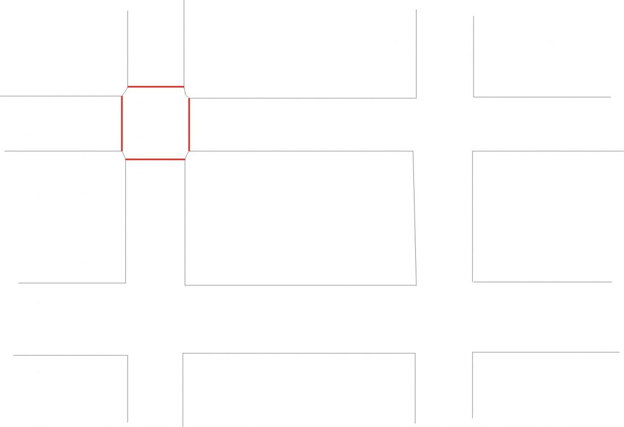
I have sidewalks centre line for a City. That is, two lines that creates the shape of a roadway. I want to create line (to represent cross-walks) in every intersections. For example, in the attachment, I have the black lines (shapefile), and I want to create the red lines in every intersections. Is there any way I can do that automatically or efficiently. Manually creating would take hours and hours as I have hundreds of intersections. Thanks.
Shafayat
Shafayat
10 Replies
01-31-2013
11:41 AM
- Mark as New
- Bookmark
- Subscribe
- Mute
- Subscribe to RSS Feed
- Permalink
I have sidewalks centre line for a City. That is, two lines that creates the shape of a roadway. I want to create line (to represent cross-walks) in every intersections. For example, in the attachment, I have the black lines (shapefile), and I want to create the red lines in every intersections. Is there any way I can do that automatically or efficiently. Manually creating would take hours and hours as I have hundreds of intersections. Thanks.
Shafayat
Question. Do you have the actual Centerlines for the roads that include Road Names of the streets? If so, I have done a process as follows:
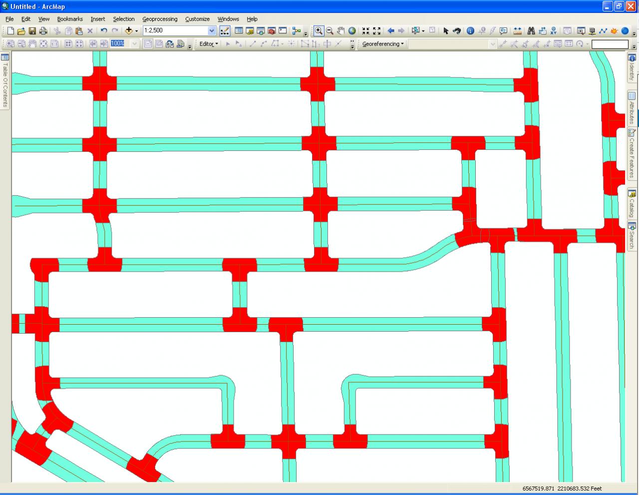
1. Features to Polygon tool. Screen Shot 1 shows the lines converted to polygons (Features to Polygons tool) and attributed and filtered to show just road interiors. Singe Centerlines within the road polygons are also shown.
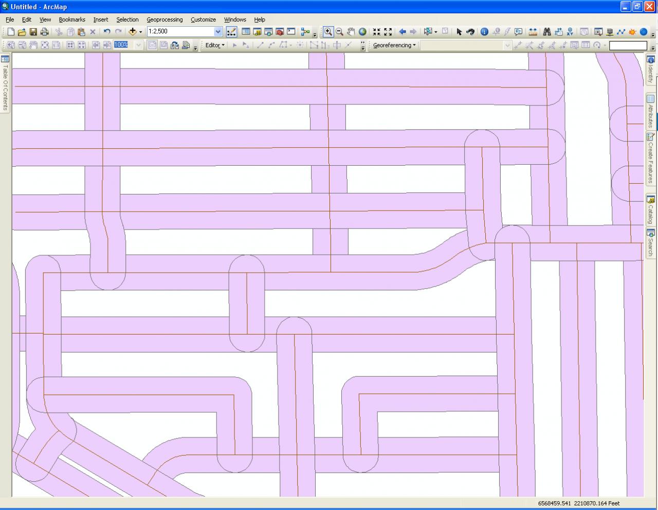
2. Buffer tool. Screen Shot 2 shows the Centerlines buffered by 75 feet. Use Road Name as the Dissolve value. Use Rounded End caps. You may have to test different buffer widths and if you have road classifications you might be able to quickly assign varying widths depending on the Road class to a field and use that for the buffer width value for better results.
3. Intersect tool. Screen Shot 3 shows the result of using the Intersect tool with the Centerline buffer output form step 2 used as an input twice and the Road casing polygon from step 1 used as an input once.
4. Definition Query. Screen shot 4 shows the definition query that will filter out just intersections from the result of Step 3. Screen shot 5 shows the resulting intersection polygons in Red overlaying the Road polygon shown in green.
See next message for further steps, since I could only upload 5 screen shots.
01-31-2013
11:54 AM
- Mark as New
- Bookmark
- Subscribe
- Mute
- Subscribe to RSS Feed
- Permalink
Thanks Richard, Yes I do have Road centre lines. Waiting for remaining attachments and procedures.
Some of the road sections are missing sidewalk centre lines. I am not sure whether this would be an issue to create polygon.
Some of the road sections are missing sidewalk centre lines. I am not sure whether this would be an issue to create polygon.
01-31-2013
11:56 AM
- Mark as New
- Bookmark
- Subscribe
- Mute
- Subscribe to RSS Feed
- Permalink
Continued from previous post.
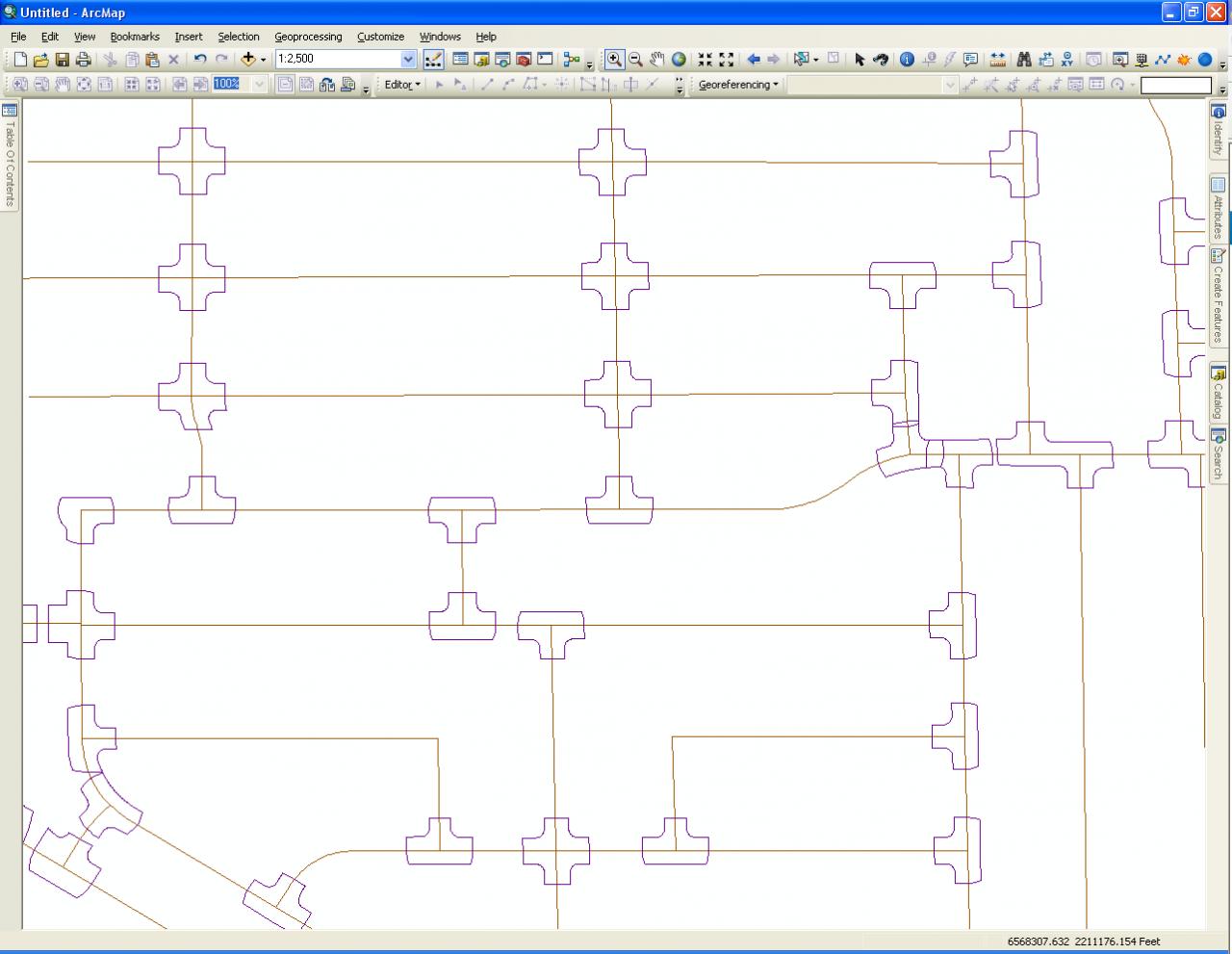
5. Feature to Line tool. Screen Shot 6 shows the result of using the Feature To Line tool on your intersection polygons (the red ones shown in step 4).
6. Preview appearance with Original line set of outlines of Roads. Screen Shot 7 shows dark green lines for your original road outlines overlaying the intersection lines exported from Step 5. The purple shows the portions of the intersections that are not overlapped.
7. Erase Tool. Use the Intersection line set from step 5 and the primary input and your original lines as the features to erase. Screen Shot 8 shows the result of the erasure.
8. The final output shown with the cased Road polygons, the original Centerlines and the purple Crosswalks. Because I kept the road names in the Intersect tool step the Crosswalks already have road names assigned that I can use to select the crosswalks.
You may have to use the Explode Multi-part feature tool on the result. And to straighten curved Crosswalks (created from the curved end caps) you could extract the two end points using the Features to Points tool with the Both Ends Option. Then use the Points to Lines tool to recreate the straight lines between the point pairs from the ID field preserved by the Features to Points tool.
I hope this helps.
01-31-2013
11:59 AM
- Mark as New
- Bookmark
- Subscribe
- Mute
- Subscribe to RSS Feed
- Permalink
Thanks Richard, Yes I do have Road centre lines. Waiting for remaining attachments and procedures.
Some of the road sections are missing sidewalk centre lines. I am not sure whether this would be an issue to create polygon.
I used a parcel layer to do the example. If the parcels excluded roads you could create a polygon that bounds the parcels using the Minimum Bounding Feature tool and then Erasing the Parcels from that Output to get a Road Casing polygon. My parcels had the road interiors, but divided at book boundaries, so I first dissolved the Road Parcels into a single parcel to get my road casing.
The parcel Casing could be an outer most boundary. You might have to mix it with your sidewalks to close all of your lines to form the road Casing polygon. Experiment to see if that is really needed.
I hope this helps.
01-31-2013
12:51 PM
- Mark as New
- Bookmark
- Subscribe
- Mute
- Subscribe to RSS Feed
- Permalink
Question. Do you have the actual Centerlines for the roads that include Road Names of the streets? If so, I have done a process as follows:
1. Features to Polygon tool. Screen Shot 1 shows the lines converted to polygons (Features to Polygons tool) and attributed and filtered to show just road interiors. Singe Centerlines within the road polygons are also shown.
2. Buffer tool. Screen Shot 2 shows the Centerlines buffered by 75 feet. Use Road Name as the Dissolve value. Use Rounded End caps. You may have to test different buffer widths and if you have road classifications you might be able to quickly assign varying widths depending on the Road class to a field and use that for the buffer width value for better results.
3. Intersect tool. Screen Shot 3 shows the result of using the Intersect tool with the Centerline buffer output form step 2 used as an input twice and the Road casing polygon from step 1 used as an input once.
4. Definition Query. Screen shot 4 shows the definition query that will filter out just intersections from the result of Step 3. Screen shot 5 shows the resulting intersection polygons in Red overlaying the Road polygon shown in green.
See next message for further steps, since I could only upload 5 screen shots.
Hi Richard,
This is what I got after creating polygon (see attached). Not sure how to filtered to show road interiors. I am fairly new in ArcGIS, Thanks for your help.
01-31-2013
12:58 PM
- Mark as New
- Bookmark
- Subscribe
- Mute
- Subscribe to RSS Feed
- Permalink
A few other notes on the output. There will always be two lines at each intersection, with the Road Names in sorted and reverse sorted orders. If only two road names meet at an intersection and you only want one line, you could select based on the sort order and either delete what you don't want or export what you do want. (I would export and leave the result unedited to be able to go back to it as a reference during clean-up).
At intersections with 3 or more names there will be more lines. Also the names that are opposite each other across an intersection with more than 2 names will place the crosswalk line in the opposing named road's location. So some process to identify these intersections and switch the attributes would be needed. Also, at 4 way named intersections you would need to deal with revising the field structure to handle more than 2 names if you want a single line at each of its Crosswalks, since at least 3 names would associate with each crosswalk.
So there will probably still be about 10 to 20 percent of the segments that need manual clean-up. I find that is typical for virtually every first-pass, broad scoped geoprocessing operation.
01-31-2013
01:18 PM
- Mark as New
- Bookmark
- Subscribe
- Mute
- Subscribe to RSS Feed
- Permalink
Hi Richard,
This is what I got after creating polygon (see attached). Not sure how to filtered to show road interiors. I am fairly new in ArcGIS, Thanks for your help.
You have to classify the polygons manually. You will need to add an attribute field (either text or number) called something line POLY_TYPE and select the first road polygon you see. Give it a value that will mean it is a road. If you use a number create a coded value domain to give a meaningful name to the value. If it text, be consistent in the spelling of the Road and Non-Road values.
One way to attribute the roads is to do the following. There should be far fewer road polygons than non-road polygons, so start with the Roads.
Select the first road polygon you see and attribute it as a Road. With this road selected, do a Select by Location using the layer to select against itself. The default Select by Location options should be fine. If the result of that selection operation was that every other polygon got selected then that polygon should be your only road polygon.
If some polygons did not get selected, reverse the selection and look at what was not touched by your road polygon(s). Find the obvious road polygon in the reversed selection and attribute it as a Road. Select all road polygons in the Attribute table (sort on that field after each edit using a Descending sort and select the all of the Road attributed group in the table). Repeat the Select by Location, reverse selection and attributing process until you have attributed all of the road polygons and every polygon is selected by the processes.
When you finish attributing the roads, select the Null polygons remain. These polygons should be your non-road polygons. Attribute them as non-roads.
You can now filter to show just the Road Polygons using a Definition Query where the field you added equals the value that means it is a road.
02-07-2013
06:47 AM
- Mark as New
- Bookmark
- Subscribe
- Mute
- Subscribe to RSS Feed
- Permalink
I am working on a similar project however I also need a way to automate the creation of the sidewalk centerlines. Any ideas other than buffering the road center line?
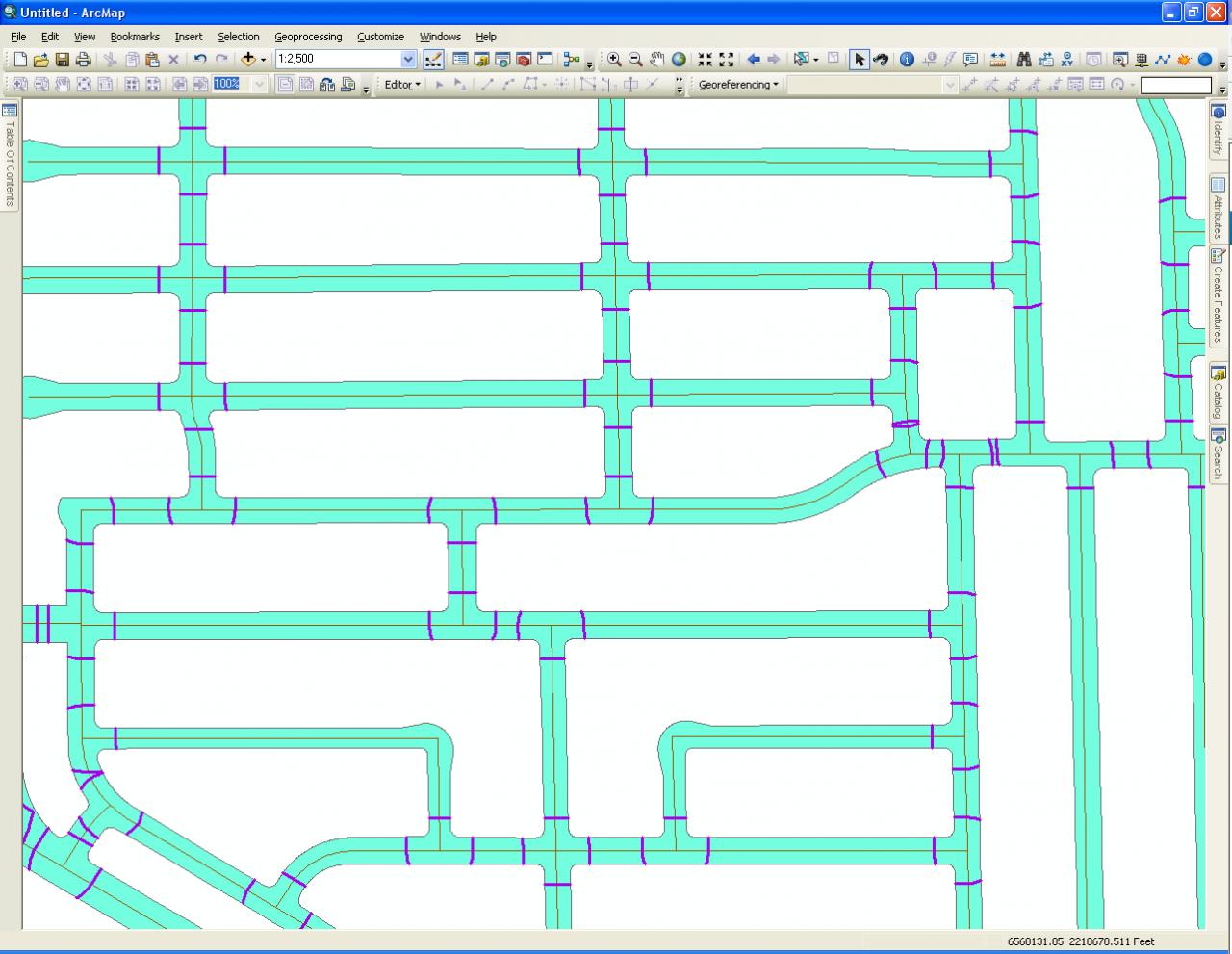
Also, I am working through the steps to create the crosswalks and already having trouble with step one. I attached a picture of my results. Any help is appreciated! [ATTACH=CONFIG]21557[/ATTACH]
Also, I am working through the steps to create the crosswalks and already having trouble with step one. I attached a picture of my results. Any help is appreciated! [ATTACH=CONFIG]21557[/ATTACH]
02-07-2013
08:11 AM
- Mark as New
- Bookmark
- Subscribe
- Mute
- Subscribe to RSS Feed
- Permalink
I am working on a similar project however I also need a way to automate the creation of the sidewalk centerlines. Any ideas other than buffering the road center line?
Also, I am working through the steps to create the crosswalks and already having trouble with step one. I attached a picture of my results. Any help is appreciated! [ATTACH=CONFIG]21557[/ATTACH]
I will address the problem with step 1 first. You have not zoomed in enough for me to tell if the input to the Lines to Polygon tool was in the correct format or not. The expected line input is a Road Casing line set, such as the frontages of Parcels lining the road. If you used a single Centerline network with lines in the middle of the road, that input will not work. So show me the line set you used at a scale where I can make out the boundary between a road outline and property outlines. Your output could be correct,but you need to do the classifying process if it is.
For the Sidewalks, I personally do not care if they trace the sidewalk exactly, so if you want an automated process to follow aerials, I don't have one. I just use Linear Referencing Events with a 30 foot offset for all roads. The lines do not overlay the aerials accurately at all and the line cross through the street intersections and do not go around the cul-de-sac bulbs. It works for my needs and got the job done for the time and budget I had, but it is not for everyone.
So for my example in this thread I just used Parcel frontage lines. Those lines do not trace sidewalks either, but they have more similarity to actual sidewalk locations.
Accurately following aerials would either require lots of time manually digitizing or paying for expensive data capture processes, such as having a vehicle laser/radar/lidar scanning your actual roads by driving them or an aerial photo conversion program that no one is going to give you for free. I have not seen any aerial interpreters that I really liked for the price, or they were not targeted for roads/sidewalks. If I knew how to program that I would charge for it and not give the code away here on the forum.