Turn on suggestions
Auto-suggest helps you quickly narrow down your search results by suggesting possible matches as you type.
Cancel
- Home
- :
- All Communities
- :
- Products
- :
- ArcGIS Enterprise
- :
- ArcGIS Enterprise Portal Questions
- :
- Re: distinguish between abutting line features wit...
Options
- Subscribe to RSS Feed
- Mark Topic as New
- Mark Topic as Read
- Float this Topic for Current User
- Bookmark
- Subscribe
- Mute
- Printer Friendly Page
distinguish between abutting line features with same color symbolization??
Subscribe
3779
8
11-19-2013 01:33 PM
11-19-2013
01:33 PM
- Mark as New
- Bookmark
- Subscribe
- Mute
- Subscribe to RSS Feed
- Permalink
Hi,
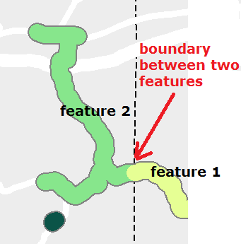
I am struggling with a symbolization challenge. I have a line shapefile depicting construction projects along a roadway centerline. The projects are color coded based on their attributes, and oftentimes two abutting projects wind up same color. It becomes impossible to tell where one ends and the other begins. I???ve included an example with two such projects, but I???ve taken the liberty to make one of them a lighter shade of green.
My initial idea was to place a thin grey border around each project. I did so by duplicating the project layer, symbolizing it grey, setting the width slightly wider, and placing it behind the primary layer. This doesn???t work???but I do like how the thin line helps the projects stand out from the map???s background.
Does anyone have any suggestions?
Thanks!
8 Replies
11-26-2013
09:18 AM
- Mark as New
- Bookmark
- Subscribe
- Mute
- Subscribe to RSS Feed
- Permalink
Thanks for the response! I tried that, and it works great...but of course now I have a new twist.
Some of the construction projects cannot be dissolved into a single feature, because I need to uniqely symbolize different parts of the project. If I apply symbolization to the layer like you describe, I end up with a border around every individual feature within the project, instead of just around the overall project.
Here's another example with two construction projects.
Any takers?
11-26-2013
09:44 AM
- Mark as New
- Bookmark
- Subscribe
- Mute
- Subscribe to RSS Feed
- Permalink
Thanks for the response! I tried that, and it works great...but of course now I have a new twist.
Some of the construction projects cannot be dissolved into a single feature, because I need to uniqely symbolize different parts of the project. If I apply symbolization to the layer like you describe, I end up with a border around every individual feature within the project, instead of just around the overall project.
Here's another example with two construction projects.
Any takers?
Symbol levels is the only thing that comes to mind to try. Other than that at some point you will come up with a scenario that requires two separate feature classes to do two different cartographic views. Or you could convert the whole thing to Linear Referencing and create as many events as you need project limits.
11-26-2013
12:41 PM
- Mark as New
- Bookmark
- Subscribe
- Mute
- Subscribe to RSS Feed
- Permalink
I think that may be the solution.
Far too many windows opened right now for the computer to handle...so I will have to try tomorrow. It seems like I had tried this already though, and was unable to get it to work correctly. I had set up a top layer (dissolved - 1 feature per project) symbolized as two offset lines, with a gap in the middle. The lines looked really "jagged" and didn't smoothly follow the curve.
I'll play around tomorrow and see if I come up with anything.
11-26-2013
12:47 PM
- Mark as New
- Bookmark
- Subscribe
- Mute
- Subscribe to RSS Feed
- Permalink
Thanks for the response! I tried that, and it works great...but of course now I have a new twist.
Some of the construction projects cannot be dissolved into a single feature, because I need to uniqely symbolize different parts of the project. If I apply symbolization to the layer like you describe, I end up with a border around every individual feature within the project, instead of just around the overall project.
Here's another example with two construction projects.
Any takers?
Something like this? Where the green and purple are different parts of the same project? (I took the liberty of modifying your screencap.)
[ATTACH=CONFIG]29391[/ATTACH]
11-26-2013
12:55 PM
- Mark as New
- Bookmark
- Subscribe
- Mute
- Subscribe to RSS Feed
- Permalink
Something like this? Where the green and purple are different parts of the same project? (I took the liberty of modifying your screencap.)
[ATTACH=CONFIG]29391[/ATTACH]
Yes, that is exactly what I'm trying to achieve.
12-03-2013
12:30 PM
- Mark as New
- Bookmark
- Subscribe
- Mute
- Subscribe to RSS Feed
- Permalink
I found a workable solution:
1) Dissolve the original features on the construction project identification field. This yields two line features in the example above.
2) Buffer these features. In my example, I created a buffer 0.7 miles on both sides of the line, with round endcaps for each line.
3) Place this polygon layer on top of everything else, and symbolize it with no fill and a thin grey outline.
The polygons/buffers do overlap (as I've shown below), and I haven't decided how to best address that...but for now this is a start. If I come up with something I'll post here.
12-03-2013
01:30 PM
- Mark as New
- Bookmark
- Subscribe
- Mute
- Subscribe to RSS Feed
- Permalink
I found a workable solution:
1) Dissolve the original features on the construction project identification field. This yields two line features in the example above.
2) Buffer these features. In my example, I created a buffer 0.7 miles on both sides of the line, with round endcaps for each line.
3) Place this polygon layer on top of everything else, and symbolize it with no fill and a thin grey outline.
The polygons/buffers do overlap (as I've shown below), and I haven't decided how to best address that...but for now this is a start. If I come up with something I'll post here.
That's kind of funny, I was just thinking about the same buffering technique this weekend. 🙂 You beat me to it. It certainly works though it might get cumbersome if the map needs to be updated regularly.