- Home
- :
- All Communities
- :
- Products
- :
- ArcGIS CityEngine
- :
- ArcGIS CityEngine Questions
- :
- Re: Who can offer an overview of how to use trim?
- Subscribe to RSS Feed
- Mark Topic as New
- Mark Topic as Read
- Float this Topic for Current User
- Bookmark
- Subscribe
- Mute
- Printer Friendly Page
Who can offer an overview of how to use trim?
- Mark as New
- Bookmark
- Subscribe
- Mute
- Subscribe to RSS Feed
- Permalink
I have been struggling quite a bit to work out how to control trim planes and how and when they will work and on what.
In this example, I've been trying to write a script for an Utzon courtyard house (see pic). Basically, it's an L-shaped building on two sides of a courtyard with a shed roof raising outward from the courtyard. Now, the way I constructed the roof (see script), it requires a split to miter the two roof parts in order to avoid overlapping geometry where they meet. But I can't make it work.
Could someone please give an overview of how to use trim? Because I obviously either don't know, or I try to make it do stuff which it can't do. In the latter case, is there an alternative way for me to reach my goal?
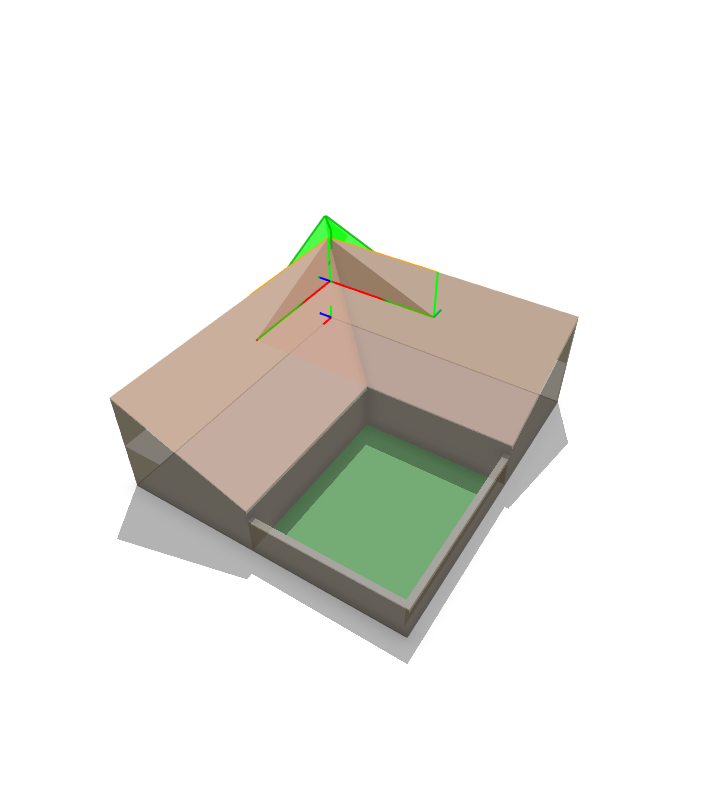
/**
 * File:    trimWalls.cga
 * Created: 23 Jun 2015 12:13:04 GMT
 * Author:  Nic
 */

version "2015.0"

attr floorH = 3
attr bldgW = 8
attr wallThickness = 0.35
attr roofAngle = 30

@Startrule
Lot --> RoofBase01 RoofBase02 shapeL(bldgW, bldgW) {shape : Footprint | remainder : rotateScope(0,180,0) Garden }

Garden--> shapeL(wallThickness, wallThickness) { shape : extrude(floorH*0.75) GardenWall | remainder : Ground }

Footprint --> extrude(floorH) Envelope

RoofBase01 --> t(0,floorH,0) rotateScope(0,90,0) split(x) { bldgW : set(trim.horizontal,true) set(trim.vertical,true) trim() roofShed(roofAngle, 2) Attic | ~1 : NIL }
RoofBase02 --> t(0,floorH,0) rotateScope(0,90,0) split(z) { bldgW : set(trim.horizontal,true) set(trim.vertical,true) trim() roofShed(roofAngle, 1) Attic | ~1 : NIL }

GardenWall --> comp(f) {side : Wall | top : Crown }
Envelope --> comp(f) {side : Wall }
Attic  --> comp(f) {vertical : Wall | top : Roof }

Wall --> color(0.9,0.8,0.6)
Crown --> color(0.7,0.7,0.7)
Roof --> color(0.9,0.7,0.6)
Ground --> color(0.2,0.6,0.2)
Solved! Go to Solution.
Accepted Solutions
- Mark as New
- Bookmark
- Subscribe
- Mute
- Subscribe to RSS Feed
- Permalink
I'm curious. Are you going to be making many houses in this style or just this one?
In any case, it is a good time to show one way of using the trim. Here is the modified rule:
version "2015.1"


attr floorH = 3
attr bldgW = 8
attr wallThickness = 0.35
attr roofAngle = 30


@Startrule
Lot -->
  #Change1: RoofBase01 RoofBase02 commented out.
  #Change2: added RoofBase rule after Garden in remainder below.
  shapeL(bldgW, bldgW) {shape : Footprint | remainder : rotateScope(0,180,0) Garden RoofBase}

Garden--> shapeL(wallThickness, wallThickness) { shape : extrude(floorH*0.75) GardenWall | remainder : Ground}

Footprint --> extrude(floorH) Envelope


#Change3: Two new rules below. Used trim planes in 2nd rule.
RoofBase -->
  t(0,floorH,0)
  extrude(bldgW)
  comp(f){back: RoofBaseWithTrim(180) | right: RoofBaseWithTrim(0)}


# Scale operation below extends extrusions past the trim planes so they can be trimmed.
RoofBaseWithTrim(rotScope) --> extrude(bldgW) rotateScope(0,0,rotScope) s('2,'1,'1) trim
  comp(f){world.up: roofShed(roofAngle) t(0,-bldgW,0) Attic}

#Change4: Removed these two rules:
#RoofBase01 --> t(0,floorH,0) rotateScope(0,90,0) split(x) { bldgW : set(trim.horizontal,true) set(trim.vertical,true) trim() roofShed(roofAngle, 2) Attic | ~1 : NIL }
#RoofBase02 --> t(0,floorH,0) rotateScope(0,90,0) split(z) { bldgW : set(trim.horizontal,true) set(trim.vertical,true) trim() roofShed(roofAngle, 1) Attic | ~1 : NIL }

GardenWall --> comp(f) {side : Wall | top : Crown }
Envelope --> comp(f) {side : Wall }
Attic  --> comp(f) {vertical : Wall | top : Roof }

Wall --> color(0.9,0.8,0.6)
Crown --> color(0.7,0.7,0.7)
Roof --> color(0.9,0.7,0.6)
Ground --> color(0.2,0.6,0.2)
Rule is attached, since copy/paste into code block above sometimes messes up code.
Chris
- Mark as New
- Bookmark
- Subscribe
- Mute
- Subscribe to RSS Feed
- Permalink
Can you show us a photo of the real house? I can tell you about using trim(), but let's make sure trim is needed for this.
- Mark as New
- Bookmark
- Subscribe
- Mute
- Subscribe to RSS Feed
- Permalink
My example is obviously a simplified version. Key issue is how to get such perpendicular shed roofs to join without overlapping geometry. Here's a photo of the real thing:

- Mark as New
- Bookmark
- Subscribe
- Mute
- Subscribe to RSS Feed
- Permalink
I'm curious. Are you going to be making many houses in this style or just this one?
In any case, it is a good time to show one way of using the trim. Here is the modified rule:
version "2015.1"


attr floorH = 3
attr bldgW = 8
attr wallThickness = 0.35
attr roofAngle = 30


@Startrule
Lot -->
  #Change1: RoofBase01 RoofBase02 commented out.
  #Change2: added RoofBase rule after Garden in remainder below.
  shapeL(bldgW, bldgW) {shape : Footprint | remainder : rotateScope(0,180,0) Garden RoofBase}

Garden--> shapeL(wallThickness, wallThickness) { shape : extrude(floorH*0.75) GardenWall | remainder : Ground}

Footprint --> extrude(floorH) Envelope


#Change3: Two new rules below. Used trim planes in 2nd rule.
RoofBase -->
  t(0,floorH,0)
  extrude(bldgW)
  comp(f){back: RoofBaseWithTrim(180) | right: RoofBaseWithTrim(0)}


# Scale operation below extends extrusions past the trim planes so they can be trimmed.
RoofBaseWithTrim(rotScope) --> extrude(bldgW) rotateScope(0,0,rotScope) s('2,'1,'1) trim
  comp(f){world.up: roofShed(roofAngle) t(0,-bldgW,0) Attic}

#Change4: Removed these two rules:
#RoofBase01 --> t(0,floorH,0) rotateScope(0,90,0) split(x) { bldgW : set(trim.horizontal,true) set(trim.vertical,true) trim() roofShed(roofAngle, 2) Attic | ~1 : NIL }
#RoofBase02 --> t(0,floorH,0) rotateScope(0,90,0) split(z) { bldgW : set(trim.horizontal,true) set(trim.vertical,true) trim() roofShed(roofAngle, 1) Attic | ~1 : NIL }

GardenWall --> comp(f) {side : Wall | top : Crown }
Envelope --> comp(f) {side : Wall }
Attic  --> comp(f) {vertical : Wall | top : Roof }

Wall --> color(0.9,0.8,0.6)
Crown --> color(0.7,0.7,0.7)
Roof --> color(0.9,0.7,0.6)
Ground --> color(0.2,0.6,0.2)
Rule is attached, since copy/paste into code block above sometimes messes up code.
Chris
- Mark as New
- Bookmark
- Subscribe
- Mute
- Subscribe to RSS Feed
- Permalink
This is genuinely cool, Chris. It opened up a whole new vocabulary of design for me. Thanks a lot!
Just to wrap up on trim(): As I understand, it only works on faces which originate from comp() as trim planes must come from something. In turn, trim planes are inherited all the way down subsequent shapes. This is not very clear from the documentation.
This makes comp() in combination with trim() an essential design tool for more complex forms.
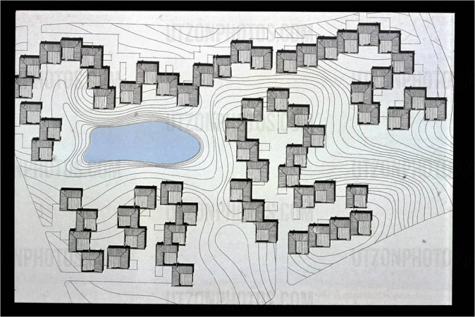
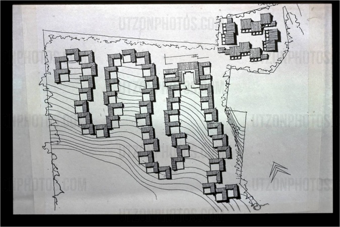
To answer your curiosity question: Yes. Utzon did a couple of housing developments where houses are arranged in chains and clusters in contoured landscapes (see pics). I am studying how to adapt his principles to other sites and terrains. This in fact opens up some more questions, but I will ask those in a new thread.
Thank again.
- Mark as New
- Bookmark
- Subscribe
- Mute
- Subscribe to RSS Feed
- Permalink
Hi guys,
Interesting. I've had to answer how to approach these meandring housing units about 3 years ago. 😉
The trim() is a cool operation, though it has the main restriction that the trim planes cannot be altered. They are only created (and are created automatically) after comp(f) - they cannot be set differently. They also cannot be rotated, ..
Cheers, keep up the cool work!
m.
Matthias Buehler
Head of 3D Technologies
twitter: @MattB3D
------------------------------------
Garsdale Design Limited
- Mark as New
- Bookmark
- Subscribe
- Mute
- Subscribe to RSS Feed
- Permalink
Hi Matt, actually it was me (same guy) who asked that question 2 years ago. I got away from this problem, and now I picked it up again. I didn't get any closer to a solution though:
I need a way to align sub-shapes to the terrain. You suggested back then to either use static shapes or graphs. Good ideas, but none of them work for my particular purpose, as my ambition is to be able to script the whole thing, rather than to import/draw specific shapes/graphs.
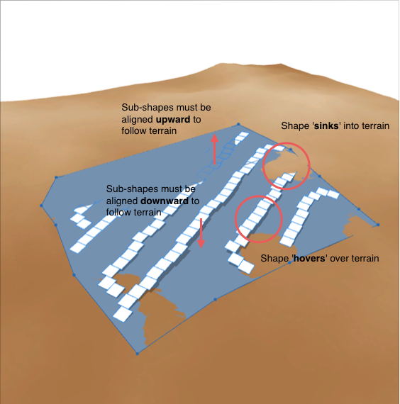
When a shape is aligned to a terrain, it seems that the surface height is interpolated from the edges rather than calculated locally from the terrain map. This means that local hills and depressions (inside the shape) will not be reflected in the alignment of the shape to the terrain (see pic).
As sub-shapes are generated from the initial shape, significant deviations from the actual terrain may occur.
My question, therefore, is if there is any way to (re-)align sub-shapes to the terrain? Would it be possible, for instance, to compare the scope.elevation of the sub-shape to the elevation attribute of the map layer at the sub-shape's location and add/subtract the difference?
- Mark as New
- Bookmark
- Subscribe
- Mute
- Subscribe to RSS Feed
- Permalink
Hey,
CGA can sample a terrain only once, at the start shape, each consecutive polygon (shape in the model hierarchy) you create with CGA can not sample itself. Therefore, what you ask is not possible to do in CGA alone.
My tip is:
1] Create the shapes as you have them in CGA
2] Convert the model to shapes
3] Align those shapes to the terrain using 'alignShapeToTerrain'
Ok?
m.
Matthias Buehler
Head of 3D Technologies
twitter: @MattB3D
-------------------------------------
Garsdale Design Limited
- Mark as New
- Bookmark
- Subscribe
- Mute
- Subscribe to RSS Feed
- Permalink
Hi, thanks for your swift reply. I am not easy to satisfy… As I would like to do a human evaluation of different rotations, spacings, etc., of the housing scheme on the terrain before settling for a final solution, this would be a tedious approach.
Meanwhile, I have been testing the "Combine Shapes" and "Convert Models to Shapes" commands in order to get a 'tiled' Shape to work from (pic). The problem with that seems to be, that the tiles need to add up with the spacings in the script in order not to generate extra sub-shapes whenever the Shape folds…
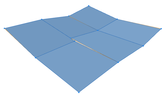
Initial shape generated with Combine Shapes command applied to 6 adjacent shapes
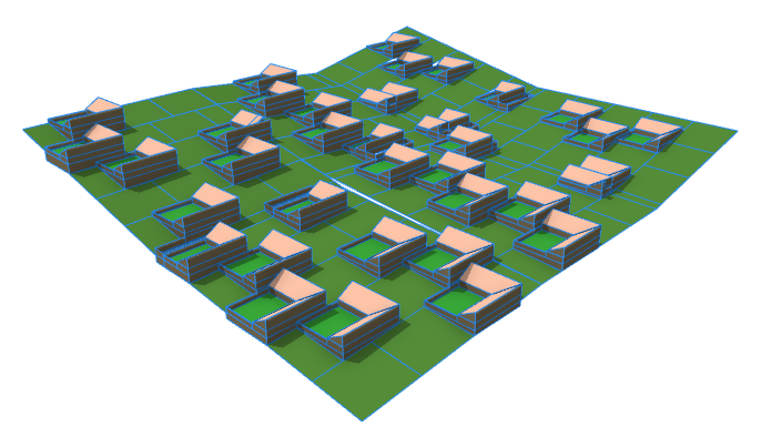
Script applied to the above Shape. Extra lines are generated where the Shape is 'stitched' together.
- Mark as New
- Bookmark
- Subscribe
- Mute
- Subscribe to RSS Feed
- Permalink
Would adding more vertices correct this? ..and if so....is there a way to add vertices to an edge using CGA?