- Home
- :
- All Communities
- :
- Products
- :
- ArcGIS CityEngine
- :
- ArcGIS CityEngine Questions
- :
- Re: Position Features from GIS data
- Subscribe to RSS Feed
- Mark Topic as New
- Mark Topic as Read
- Float this Topic for Current User
- Bookmark
- Subscribe
- Mute
- Printer Friendly Page
- Mark as New
- Bookmark
- Subscribe
- Mute
- Subscribe to RSS Feed
- Permalink
Hi All,
We are creating a large GIS model and then we wish to use that model to inform procedures to turn the model to a 3D representation.
As part of this process we have used the Spatial ETL Tool in ArcGis to read a set of Room Layout Plans and create simple GIS features including rooms and floor outlines.
We have then used this data to create a Room by Room model and a Floor by Floor model within City Engine 2014/2015 by taking our GIS File Geodatabase and providing rules to create simple and textured buildings. This appears to work well and show potential as a route to model a complete area.
We understand how we can use CGA scripts to texture and add features to the buildings. What we not however sure how to do the following;
The CAD drawings contain the locations of features such as Windows and Doors. We can import this from the CAD drawings and load into a FileGeodatabase without too much problem. What we are not sure about how to do is to use this data within the CGA scripts to accurately position window and door features within the building structures.
Can anyone help?
Thanks,
Paul
Solved! Go to Solution.
Accepted Solutions
- Mark as New
- Bookmark
- Subscribe
- Mute
- Subscribe to RSS Feed
- Permalink
Hi Chris and Paul,
Yah, that is dead on. Either you have to have 3 stacked polygons, one for the wall to bottom of window, window up, and then window to top of wall or you make a rule that creates a blended piece of geometry. In the case of Abu Dhabi's BDMS we create a rule where they included with in the polygon the distance to bottom of sill, and then the height of the window. The top was just filled in with wall.
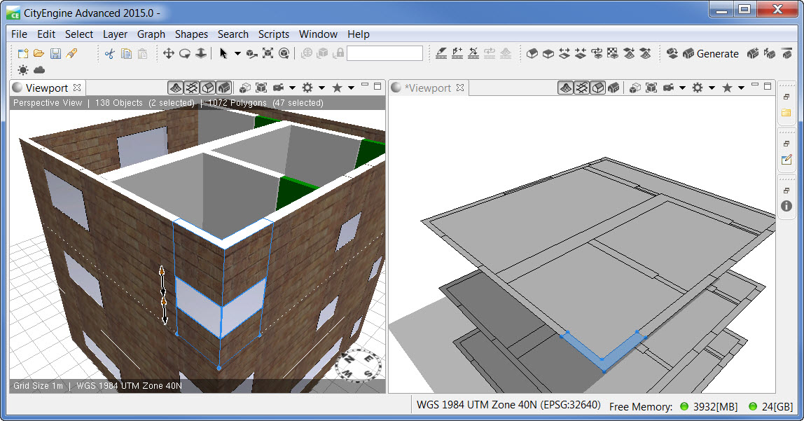
We exposed some handles so the values could be interactively changed from the view port.
EW
- Mark as New
- Bookmark
- Subscribe
- Mute
- Subscribe to RSS Feed
- Permalink
The windows and doors must be closed polygons to run rules on them. If the CAD data is 3D and the windows have proper z values (y in CE) then that is good. Otherwise you can have an attribute applied per each level of windows that indicates elevation for the windows. I'd suggest having multiple floors on their own layer, so that you can lock or hide those layers when not in use, since they might all be overlapped if no z is present. You will need CE 2015 for these features, and 2015 also imports CAD layers, where 2014.1 would collapse CAD layers into one.
- Mark as New
- Bookmark
- Subscribe
- Mute
- Subscribe to RSS Feed
- Permalink
Thanks Chris, That's a great help.
I have imported all the Cad files into a File Geodatabase. There is no problem making the windows as polygons and setting the z value. Where I am stuck is that the floor boundary is a different feature in the GIS to the window.
If I create the outside wall then the cga rule cannot interrogate (or at least I don't know how to) the window features to see if there needs to be a window inserted. If I take the approach of taking the windows as standalone entities then I will need to make the walls first and then create a hole in the already constructed wall for the window....Is that possible?
Hope this makes sense .... In the GIS FGDB in the imported Cad I have a feature for walls and a sepearate feature class for windows, If I need to think about it differently I can.
Thanks,
Paul
- Mark as New
- Bookmark
- Subscribe
- Mute
- Subscribe to RSS Feed
- Permalink
Paul,
You are correct about one shape no interrogating another. They can only check for occlusion - where shapes intersect - and that is only a true false test to see if shapes intersect or touch or are inside of another. I worked with this type of rule recently, and how they solved it was that the window shape was responsible for generating the wall under and above the window. So the wall features were not centerline based, but were a polygon with wall thickness.
Eric Wittner, You've seen this problem recently. Any advice for Paul?
Thanks,
Chris
- Mark as New
- Bookmark
- Subscribe
- Mute
- Subscribe to RSS Feed
- Permalink
Hi Chris and Paul,
Yah, that is dead on. Either you have to have 3 stacked polygons, one for the wall to bottom of window, window up, and then window to top of wall or you make a rule that creates a blended piece of geometry. In the case of Abu Dhabi's BDMS we create a rule where they included with in the polygon the distance to bottom of sill, and then the height of the window. The top was just filled in with wall.
We exposed some handles so the values could be interactively changed from the view port.
EW
- Mark as New
- Bookmark
- Subscribe
- Mute
- Subscribe to RSS Feed
- Permalink
I should clarify, the collapsed all their overlapping geometries from the CAD down to planar polygons. Then classed them by type, and we wrote a rule that contained those types. Windows with cill height and total window height that filled in the top with wall. Doors with door height that filled in the top with wall. Interiors walls, exteriors walls, spaces, hallways, etc.
EW
- Mark as New
- Bookmark
- Subscribe
- Mute
- Subscribe to RSS Feed
- Permalink
Thanks. I can see how that works. It is a shame I cannot punch through but if we cannot then will need to try this approach.
It does mean I need to process all the CAD files in a different ways to get the wall and window polygons as they are just line features at the moment. That should be possible though.
Thanks for your help,
Paul
- Mark as New
- Bookmark
- Subscribe
- Mute
- Subscribe to RSS Feed
- Permalink
Yah ... some creative model builder work is in order.
Take floor layer, feature to polygon, get floor polygon.
Take floor walls, feature to polygon, then erase walls from floor
Optional: negative buffer floor by 0.25, union with walls
Gives you thin exteriors walls as seperate polys from interior walls.
Take window layer, feature to polygon, then erase windows from walls.
May have some challenges here if windows just represent panes, and fall within the wall.
Take doors layer, feature to polygon, erase from floor
Multipart to singlepart on remaining polys of floor to get rooms/hallways.
May want to poly and erase other features such as support columns, stairs, elevators, etc.
Process needs to be done floor by floor.
When done, add field height as double to all feature classes.
Calculate field height at floor z.
Feature to 3D by Attribute data to burn the Z values into the geometry.
- Mark as New
- Bookmark
- Subscribe
- Mute
- Subscribe to RSS Feed
- Permalink
Thanks for this. I am going to busy with my current skill level. The logic
sounds good though.
I may try this with the Spatial ETL tool as we had to use this to import
the CAD rather than model builder. Will give it a go with this or model
builder with the imported features.
*Kind regards,
Paul Bushnell
Estates Works Manager
The University of York
Providence House
Heslington, York YO10 5ZF
Tel 01904 322172*
- Mark as New
- Bookmark
- Subscribe
- Mute
- Subscribe to RSS Feed
- Permalink
Thanks Eric.
I have got stuck on something really silly though. The room boundaries were
originally Polygons and the rooms were solid blocks. I am able to create
lines around the room boundaries but what I am struggling with is
converting the room boundary lines to wall polygons with a thickness. The
feature to polygon reconstructs the whole room as a polygon which isn't
what we want.
*Kind regards,
Paul Bushnell
*