- Home
- :
- All Communities
- :
- Products
- :
- ArcGIS CityEngine
- :
- ArcGIS CityEngine Questions
- :
- Re: How to assign elevations
- Subscribe to RSS Feed
- Mark Topic as New
- Mark Topic as Read
- Float this Topic for Current User
- Bookmark
- Subscribe
- Mute
- Printer Friendly Page
How to assign elevations
- Mark as New
- Bookmark
- Subscribe
- Mute
- Subscribe to RSS Feed
- Permalink
I do have another question for you afterall. I have brought in a layer of all of the building floors, it contains information about the elevation of the floor of the floor and also has the height of the floor. This is very important because our buildings have irregular interstitials that have been requested to be modled true to form. I was able to create a rule to extrude each floor by the height attribute. Im stuck on trying to determine how to assign the elevations in the attributes as the "heightmap", the elevation that floor should sit on. I want this to be independant of my terrain so I assume that it has to be added to the rule. I found some information online stating that there was a way to do this but the token settings.setHeightmap say that it is undefined. Very confused: below is an example of where Im currently at:
#This attribute should be "sourced" to the object attribute
attr Height = 0
attr Elevation = 0
@StartRule
Lot -->
extrude (Height)
volume.
This is the example I atempted to use but I guess I dont understand it:
alignShapes(self, shapes, settings=None)Aligns a set of shapes.
@param shapes: The set of shapes to align.
@param settings: The align settings. Omit to use default settings. (default = None).
@note: # align shapes of layer 'Lots' to layer 'Heightmap'
lotLayer = ce.getObjectsFrom(ce.scene, ce.isLayer, ce.withName("'Lots'"))
settings = AlignShapesSettings()
settings.setHeightmap('Heightmap')
settings.setAlignFunction(AlignShapesSettings.TRANSLATE_TO_MIN)
ce.alignShapes(lotLayer, settings)
- Mark as New
- Bookmark
- Subscribe
- Mute
- Subscribe to RSS Feed
- Permalink
Hi Jacqueline,
When you bring the shape layer in, which are all individual floors of a building (or buildings?) are the shapes flat at zero elevation? And you say they have a Height and Elevation object attribute, and regardless of the terrain you want the floor at that elevation?
Chris
- Mark as New
- Bookmark
- Subscribe
- Mute
- Subscribe to RSS Feed
- Permalink
Yes that is correct. I want the base of each floor to sit at the elevation specified in the Elevation attribute field. From there I will extrude them based on the Height attribute field.
- Mark as New
- Bookmark
- Subscribe
- Mute
- Subscribe to RSS Feed
- Permalink
The rule below will do it. To explain further what you are showing in you original post, the rule at the top is almost there. It just needs a t(x,y,z) which translates (moves) the model relative to its current position. There is an absolute translation, but you only want the y to be absolute, not x and z. Also, if your shapes are not coming in at elevation zero, then see the comments in the rule below, for instructions on moving them down. The code you have at the end of your post is python, which is not needed since the AlignShapesToTerrain command is available in the Shapes menu, and on the toolbar. Python can be used to work with many shapes, while CGA runs on one shape at a time.
version "2015.1"
# First, select all shapes and align them to y=0,
# using Shapes > AlignShapesToTerrain > Project All, y=0
attr Height = 0
attr Elevation = 0
@StartRule
BuildingFloorShape -->
# Move shape to elevation, relative to the current zero elevation.
t(0,Elevation,0)
# Extrude shape to make floor volume.
extrude(Height)
- Mark as New
- Bookmark
- Subscribe
- Mute
- Subscribe to RSS Feed
- Permalink
Ok that worked in regards to the extrusion but the foot print is still showing at y=0 along with a shadow. How do I remove the footprint from y=0 plain? I added a screen shot of what Im talking about. I drew a pink box around one of the most obvious chunk of buildings. 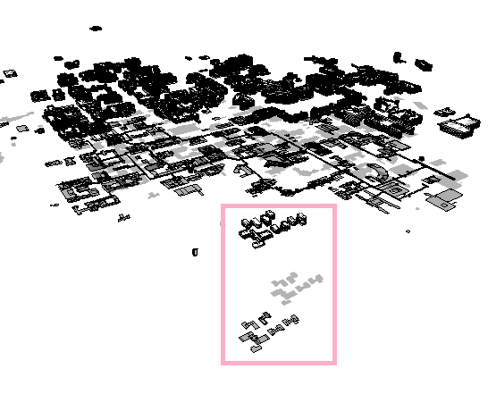
- Mark as New
- Bookmark
- Subscribe
- Mute
- Subscribe to RSS Feed
- Permalink
Here is another screen shot where I put in yellow the portion that I dont want to see. Can I define that in the rule as to not be shown? 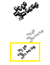
- Mark as New
- Bookmark
- Subscribe
- Mute
- Subscribe to RSS Feed
- Permalink
Jacqueline,
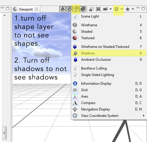
These are settings you can change in the viewport toolbar. No rules involved. ![]() See image below for two buttons which will turn off the shapes and the shadows. The shadow control is in the gear shaped icon.
See image below for two buttons which will turn off the shapes and the shadows. The shadow control is in the gear shaped icon.
Chris
- Mark as New
- Bookmark
- Subscribe
- Mute
- Subscribe to RSS Feed
- Permalink
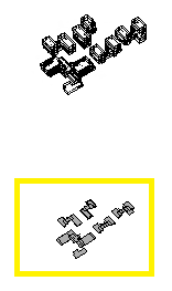
I know how to turn the shadows off. I dont mind the shadows. Still confused about what you are saying in regards to the shapes. If I turn off the shapes in the scene window it turns off all of the shapes not just the remnants that remained at y=0. Im going to add the screen shot again wit the shadows turned off incase they are confusing you. In the picture the two ittems that you are seeing are BOTH the same shape. I cannot turn one off independantly of the other use the check box. The items in yellow are where the buildings appear prior to having the rule applied (at y=0). Once the rule is applied the items that are not in the yellow box are generated. I want to not see the items in yellow. Again turing off the shapes in the scene window doesnt work because these are the same shape. I tested using the selection tool aswell if I select one the other is automatically selected and the Scene window also only shows one item selected.
Does that make more sense?
- Mark as New
- Bookmark
- Subscribe
- Mute
- Subscribe to RSS Feed
- Permalink
Yes, you are making total sense. If I am understanding you correctly, the shapes in the yellow box are the imported shapes that you applied the rule to, and the extruded buildings that are above the yellow box are the models generated from those shapes. And yes, if you turn off their layer in the scene window, then both the shapes and their generated models will not be visible. And if you select either the shape or the model, both will be selected. You cannot turn off the original shapes from within the rule. If you want to see the models, but not the shapes, your only option is to toggle off all of the shapes using the button indicated in the image below, and you must leave the models on (4th toggle from left).
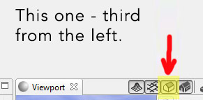
This will turn off all shapes. Please let me know if I'm confused about this.
- Mark as New
- Bookmark
- Subscribe
- Mute
- Subscribe to RSS Feed
- Permalink
Ok I guess I was the one that was confused that makes more sense! Thank you.