- Home
- :
- All Communities
- :
- Products
- :
- ArcGIS CityEngine
- :
- ArcGIS CityEngine Questions
- :
- How can I get unique building IDs and exact buildi...
- Subscribe to RSS Feed
- Mark Topic as New
- Mark Topic as Read
- Float this Topic for Current User
- Bookmark
- Subscribe
- Mute
- Printer Friendly Page
How can I get unique building IDs and exact building heights?
- Mark as New
- Bookmark
- Subscribe
- Mute
- Subscribe to RSS Feed
- Permalink
Hi,
I am looking for a way to get the height of selected buildings, either in the report, inspector, or as a .csv, to later make height adjustments for specific buildings.
My goal is to compute stats of buildings along specific street sections and then modify the height of certain buildings - ideally, I'd get a table with an ID for every building and its height.
I tried to get the heights manually by converting each model to a shape, selecting the highest point, read the y-vertex value from the inspector and save that into an excel file, and then modify the y-vertices in a copy of the scene - that approach worked, but is not really feasbile given the amount of buildings.
I am a total cga beginner.. I could manage to get the cga file I am using (a modified version of International City.cga, created on 6 Nov 2013 by Esri R&D Center Zurich) to show the attribute buildingHeight in the inspector, however, modifying the value does not change the height of a building and the code line for unhiding attr buildingHeight in the inspector is not really where it would be logical. This is part of the code:
######################################################
# control attributes (set by user or mapped)
#
@Group("Building") # ("Building",1) deleted, seemed unnecessary
@Order(1) @Range("Highrise Building","Office Building","Apartment Building","Residential","Open Space") @Order(1)
attr Type = getType
#@Order(2) @Range(0.5,10) # my comment: I increased the range from (0.5,2) to (0.5,10)
attr HeightFactor = 1
# my comment: the following showed building height in the inspector but really weird numbers
# attr HeightFactor = getBuildingHeight
# the following 2 lines erase all of the CGA annotations for rules in the inspector...
#@Order(3) @Range(1,400) # I increased the range from (0.5,2) to (0.5,10)
#attr buildingHeight = HeightFactor
# @Group("Trees", 3) #,3 deleted (didnt know what it does)
@Group("Trees")
@Order(1) @Range("None","Fan","Model","Analytical") @Description("Do not generate Models for whole city i.e. take care with polygon counts!")
attr ShowTrees = "Fan"
@Order(2) @Range("Random Forest","Tropical","Zone 6 Trees")
attr Mix = "Zone 6 Trees"
###################################################
# Residential
#
# unhide the attribute building height in inspector like this:
attr buildingHeight = 1# getBuildingHeight didn't work
# these attributes are hidden in the inspector:
@Hidden
attr groundFloorHeight = 0
Can anyone help?
- Mark as New
- Bookmark
- Subscribe
- Mute
- Subscribe to RSS Feed
- Permalink
If your shapes already have some sort of unique ID in their attributes, you could use those. You can access the height with scope.sy. If you don't have any ID, you could probably get away with using the seedian or better yet initialShape.origin.px.
This example would print the building seedian and then its height (which is 5 here) in the console window.
Lot -->
extrude(5)
print(seedian)
print(scope.sy)- Mark as New
- Bookmark
- Subscribe
- Mute
- Subscribe to RSS Feed
- Permalink
If you don't already have unique IDs, another solution would be to generate them by exporting your shapes (File -> Export Models -> FileGDB -> Export Features = Shapes) to a GDB and importing them back into CityEngine again. Then, each shape will have a unique object attribute called OBJECTID. But, if you have dynamic shapes, then this will ruin the dynamic nature of your shapes (they won't be connected to the streets anymore).
- Mark as New
- Bookmark
- Subscribe
- Mute
- Subscribe to RSS Feed
- Permalink
Thank you Cheryl.
I would like to modify the height of a building while keeping the facade the same.
I have tried your suggestion, but this approach doesn't work for me, since if I don't have dynamic shapes anymore, the textured facade (the image) just gets stretched (see red arrow below):

This changes the appearance of the building too much for my purpose.
My main rule file imports the Facade Textures.cga file (from ESRI.lib), where the texturing is calculated so that the facade image fits the width and height of the building. I would need this here too, but as far as I know this can only be done for models, and not for point-like geometry?
- Mark as New
- Bookmark
- Subscribe
- Mute
- Subscribe to RSS Feed
- Permalink
Thank you.
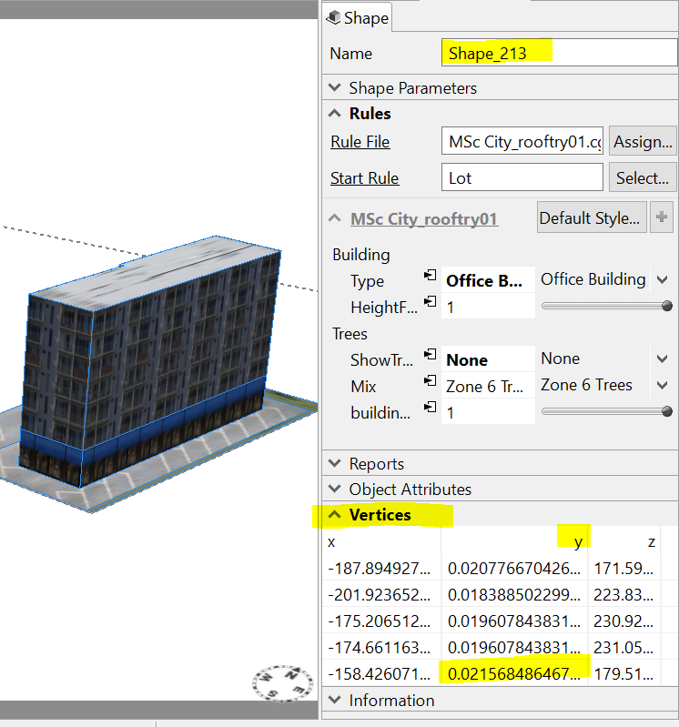
I have assigned a unique shape name to all my shapes now (by first selecting all buildings, then by Edit > Make Names Unique) which get printed to the CGA console.
Code snippet:
@StartRule
Lot -->
translate(rel,world,0,Street_Modern_Standard.SidewalkHeight,0)
LotAligned
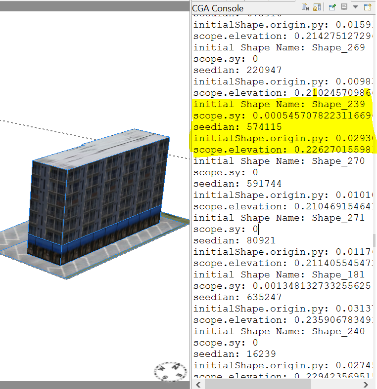
print("initial Shape Name: " + initialShape.name) # prints the unique shape name to the CGA console
print("scope.sy: " + scope.sy)
print("seedian: " + seedian)
print("initialShape.origin.py: " + initialShape.origin.py)
print("scope.elevation: " + scope.elevation)
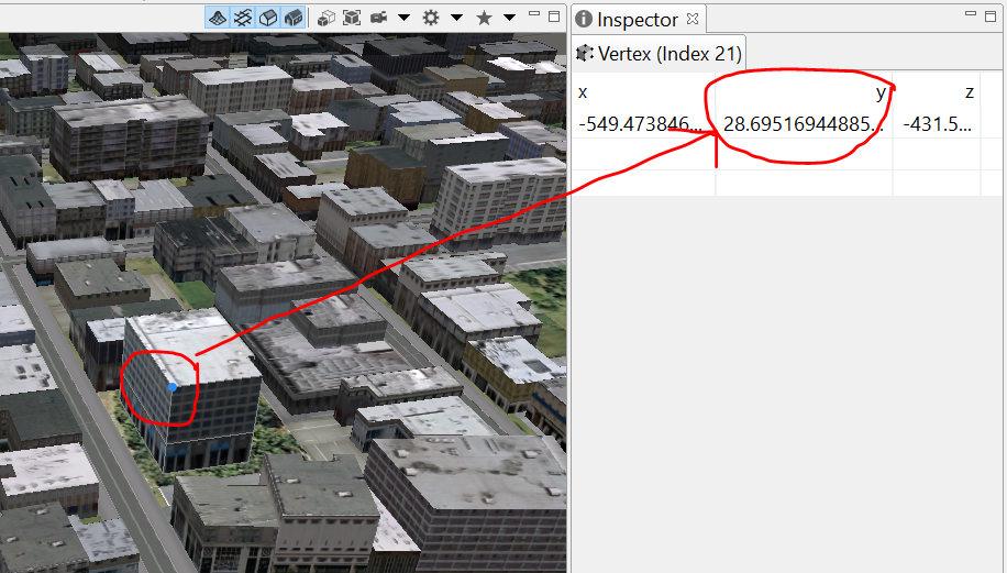
When I convert the models to shapes and select the building at its highest point, I can access the y-vertex value in the inspector, which I assume is the height of the building (23.907):

However, neither the scope.sy, initialShape.origin.py, nor scope.elevation values printed to the console correspond to 23.907:
This is quite confusing. Any suggestion?
- Mark as New
- Bookmark
- Subscribe
- Mute
- Subscribe to RSS Feed
- Permalink
For the GDB export, I actually meant to export only the 2D shapes underneath the buildings and not the full building models. To do this, set the export option Export Features = Shapes.
Then, you can apply a rule to these 2D shapes which extrudes them to the building height.
I think there is a misunderstanding of what the numbers mean in the Vertices section in the Inspector. These are the vertices of the initial shape (Rule-Based Modeling (CGA Shape Grammar) ). The y values that you see in the Inspector are in world coordinates, or the CityEngine coordinate system. In your example, the vertices in this section are the vertices of the initial shape onto which the building rule was applied. Any geometry created by the rule will not be in this vertex list. This means that the tallest point of the building is not in this list since the building is created by the rule; the building is a model.
In one screenshot (with the yellow and red arrows), you converted the building models into shapes and then tried to move the vertices to increase the height of the building. This changed the vertices of the shapes. The rule applied to these shapes seemed to just stretch the facade texture to fit the new shape. I do not recommend converting to shapes and changing the building height by changing the values in the Vertices section in the Inspector.
Instead, I would recommend writing a rule that is applied to a 2D shape (e.g. building footprint). This rule would extrude the shape to the building height. If the building height is an attribute, you can change this value for each shape.
attr height = 10
Lot -->
extrude(height)
print("height = " + scope.sy)If you wanted to split one lot (2D initial shape) into three separate building footprints, you could manually do this with the Polygonal Shape Creation tool. Then, you could apply the rule to each of these footprints.
In other screenshots (where the y values of the vertices are about 0.02 and the printed scope.elevation is 0.22), the y values are the y values of the vertices of the initial shape in world coordinates, and the scope.elevation value is the y value in world coordinates of the current geometry created in the rule. In the rule, there is a translate operation which translates the geometry in the y direction by the amount Street_Modern_Standard.SidewalkHeight, which equals 0.2. Therefore, the scope.elevation value after this translation operation is going to be the initial shape's y value + the translation amount which is 0.02 + 0.2 = 0.22. This is why scope.elevation = 0.22. In the screenshot, scope.sy is almost zero because the geometry at that point in the rule is nearly planar or flat.
Printing scope.sy after the extrude operation should give you the height of the building.
This should also explain that in one of the screenshots (where y = 23.907), the y value here is not the height of the building but rather the y value of the initial shape + the height of the building. Remember that in this screenshot, the building model was converted to a shape, and that's why the vertices appear in the Vertices section in the Inspector.
- Mark as New
- Bookmark
- Subscribe
- Mute
- Subscribe to RSS Feed
- Permalink
Thank you for clarfiying!
Manually changeing the lot size with the polygonal shape creation tool worked. Sometimes there's still more than 1 building on 1 lot, I couldn't find that part in the rule file that I had, so I have decided to take another pre-built CE project that contains only 1 building per footprint. It's quite convenient that the new project already has the attribute "building height".
- Mark as New
- Bookmark
- Subscribe
- Mute
- Subscribe to RSS Feed
- Permalink
Changing the height using an attribute (rather than converting to shapes and editing vertices) is the way to go, so finding a rule that lets you do that is probably a better solution.
The Building_From_Footprint.cga rule in ESRI.lib is a rule that lets you change the eave height and the ridge height of your building. Maybe this is of interest to you?
- Mark as New
- Bookmark
- Subscribe
- Mute
- Subscribe to RSS Feed
- Permalink
Thank you Cheryl, that's good to know!