- Home
- :
- All Communities
- :
- Developers
- :
- Python
- :
- Python Questions
- :
- Re: Rotate Polylines based on Existing Polyline An...
- Subscribe to RSS Feed
- Mark Topic as New
- Mark Topic as Read
- Float this Topic for Current User
- Bookmark
- Subscribe
- Mute
- Printer Friendly Page
Rotate Polylines based on Existing Polyline Angles
- Mark as New
- Bookmark
- Subscribe
- Mute
- Subscribe to RSS Feed
- Permalink
Hey Everyone,
Currently what I am trying to do is rotate polylines in certain grid sections to the same orientation of existing polylines in that grid. This seems to be quite complicated as I have looked quite extensively for something like this, but to no success. Currently right now I have implemented a tool that was posted here arcpy - Drawing parallel lines inside polygons (Well Paths) using ArcGIS Desktop? - Geographic Infor... now this works for me and does what it should... but here is my problem posted below.
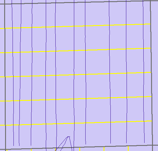
The grid lines that were drawn automatically (yellow) are horizontal where as I would like them be vertical. If there is a way through arcpy or other tools where I can rotate these lines to be the same direction of polylines that are currently there. This is just one example, this happens many times in different areas.
Thank you!
Solved! Go to Solution.
Accepted Solutions
- Mark as New
- Bookmark
- Subscribe
- Mute
- Subscribe to RSS Feed
- Permalink
Here's some code that I have been experimenting with that may give you some ideas. It takes a polygon feature class and creates a layer of points marking each polygon's centroid. It also creates a line through the centroid at a given azimuth.
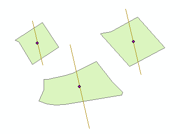
From here, you need to add additional parallel lines and clip them to the polygon.
import arcpy
import math
def draw_line(point, distance, bearing):
angle = 90 - bearing
bearing = math.radians(bearing)
angle = math.radians(angle)
cosa = math.cos(angle)
cosb = math.cos(bearing)
x1, y1 = \
(point[0] + (distance * cosa), point[1] + (distance * cosb))
x2, y2 = \
(point[0] - (distance * cosa), point[1] - (distance * cosb))
return [[x1, y1], [x2, y2]]
polyFC = "poly_line" # the polygon feature layer
azimuth = 347
desc = arcpy.Describe(polyFC)
SR = desc.spatialReference
arcpy.env.overwriteOutput = True
arcpy.env.outputCoordinateSystem = SR
points = []
lines = []
with arcpy.da.SearchCursor(polyFC,['SHAPE@']) as cursor:
for row in cursor:
centroid = row[0].centroid
points.append(arcpy.PointGeometry(centroid))
dist = 0
for part in row[0]:
for pnt in part:
cent_vert_dist = arcpy.PointGeometry(pnt).distanceTo(centroid)
if cent_vert_dist > dist:
dist = cent_vert_dist
# far_point = arcpy.PointGeometry(pnt)
# points.append(far_point)
feature_info = [ draw_line((centroid.X, centroid.Y), dist, azimuth) ]
for feature in feature_info:
lines.append(
arcpy.Polyline(
arcpy.Array([arcpy.Point(*coords) for coords in feature])))
arcpy.CopyFeatures_management(points,'in_memory\points')
arcpy.CopyFeatures_management(lines,'in_memory\lines')- Mark as New
- Bookmark
- Subscribe
- Mute
- Subscribe to RSS Feed
- Permalink
The tool you mention creates a hull rectangle for each polygon and makes the lines parallel to what is determined as the longest side of the hull rectangle. Are most or all of your polygons rectangles (and not irregular shapes)? If they are rectangles, would you always want the lines parallel to the most north/south sides?
- Mark as New
- Bookmark
- Subscribe
- Mute
- Subscribe to RSS Feed
- Permalink
Hey Randy,
Most are rectangles yes with a few irregular shapes. How would I go about changing this so it would always draw the lines parallel to the most north/south sides? I am not sure if that will work but its worth a shot to try and see how it looks visually.
- Mark as New
- Bookmark
- Subscribe
- Mute
- Subscribe to RSS Feed
- Permalink
Here is some of the code from the stackexchange page (the part where it loops through the polygon feature):
for row in arcpy.da.SearchCursor(polyFC, ["SHAPE@"], spatial_reference=SR):
# create inner buffer
polyBuff = row[0].buffer(buffNum * -1)
# create hull rectangle to establish a rotated area of interest
coordSplit = row[0].hullRectangle.split(' ')
# collect corner coordinates
coordList = arcpy.Array([arcpy.Point(coordSplit[0],coordSplit[1]),arcpy.Point(coordSplit[2],coordSplit[3]),arcpy.Point(coordSplit[4],coordSplit[5]),arcpy.Point(coordSplit[6],coordSplit[7]),arcpy.Point(coordSplit[0],coordSplit[1])])
# create lines from hull rectangle
currentLines = []
for pointNum in range(0,4):
arcpy.Array([coordList.getObject(pointNum),coordList.getObject(pointNum+1)])
hullRecLine = arcpy.Polyline(arcpy.Array([coordList.getObject(pointNum),coordList.getObject(pointNum+1)]))
currentLines.append(hullRecLine)
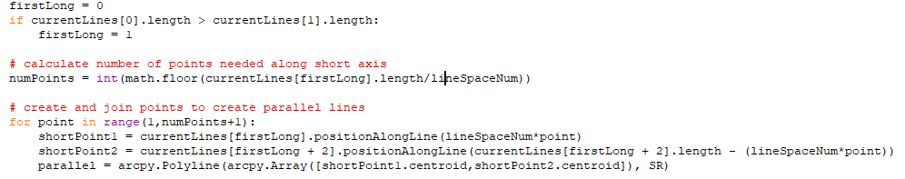
# compare first and second line to determine if first line is short or long
firstLong = 0
if currentLines[0].length > currentLines[1].length:
firstLong = 1
# calculate number of points needed along short axis
numPoints = int(math.floor(currentLines[firstLong].length/lineSpaceNum))
# create and join points to create parallel lines
for point in range(1,numPoints+1):
shortPoint1 = currentLines[firstLong].positionAlongLine(lineSpaceNum*point)
shortPoint2 = currentLines[firstLong + 2].positionAlongLine(currentLines[firstLong + 2].length - (lineSpaceNum*point))
parallel = arcpy.Polyline(arcpy.Array([shortPoint1.centroid,shortPoint2.centroid]), SR)
# intersect parallel lines with buffer
parallelBuff = parallel.intersect(polyBuff,2)
parallels.append(parallelBuff)
In lines 6-17, the code is creating a hull rectangle and getting the lines that make up the rectangle. At lines 20-22, it is comparing the lines to see which side is the long side. The code then goes on to draw the lines.
If you were to compare the starting xy coordinates and ending coordinates of the first and second lines, you should be able to determine which is the most northerly of the lines. Then set the index ( firstLong ) to indicate which line to use.
- Mark as New
- Bookmark
- Subscribe
- Mute
- Subscribe to RSS Feed
- Permalink
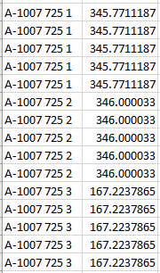
hmm yeah I see what you mean, that could work! Also to note, I just received more data within this grid section where I have been given an ID for the section block and the average azimuth that current polylines that are drawn within it are. For example, BLOCK ID 1, Average Azimuth 347.57. How would I be able to introduce a portion where if the Block ID contains an Azimuth attribute, draw lines with the same spacing currently you set but with the angle that is specified within the table. Any help would be appreciated.
- Mark as New
- Bookmark
- Subscribe
- Mute
- Subscribe to RSS Feed
- Permalink
It should be possible to use the polygon's centroid and draw lines using an azimuth. Several of Dan Patterson's Py... blog articles give code examples that might work into this project (or at least, to provide some ideas).
Geometry: Points in the field calculator
(see: Line direction or Azimuth to Compass Bearing and Convert Azimuth to Compass Bearing sections)
Origin, distances and bearings... geometry wanderings
Numpy Snippets # 3 ... Phish_Nyet ... creating sampling grids using numpy and arcpy
- Mark as New
- Bookmark
- Subscribe
- Mute
- Subscribe to RSS Feed
- Permalink
Hey Randy, those are helpful thank you for that! I have kind of narrowed it down to where I need to change the code.
if I could somehow change it where, If I know the azimuth is 347 for example for lines drawn in that section, then I know the lines should be oriented N-S with that degree on them. This has proved to be extremely challenging, at least for my level of python knowledge.
- Mark as New
- Bookmark
- Subscribe
- Mute
- Subscribe to RSS Feed
- Permalink
Adam, that is the code that creates the polyline using the existing points etc.
You could... use angleAndDistanceTo (other, {method}) ...
from Polyline—ArcPy classes | ArcGIS Desktop
to find out what the current angle of the polyline is.
You could use pointFromAngleAndDistance (angle, distance, {method})
to replace your 2nd point.
The only downside I can think of is that you may need to decide whether you are going to rotate the existing polylines from the first point, the middle point or the last point on the existing polyline.
My Sampling Frameworks toolset allows you to create polygons... but in your case, you would want rotated rectangles, but you only want 2 of the side... you could at least pull out my code for a look-see to see if you can modify i... I haven't had any use cases for this sort of thing (ie parallel rotated lines, but I will put it on the 'todo' list
- Mark as New
- Bookmark
- Subscribe
- Mute
- Subscribe to RSS Feed
- Permalink
Hey Dan thanks for the suggestions, I will play around with those two functions and see what I can do. I am thinking of not even rotating them, If I could just draw them based on azimuth direction from the start that would be great. I have been provided a table that outlines the grid, each section in that grid has its own ID and the average azimuth within each section. For example
If I could draw the lines from the start with these azimuth bearings that would be helpful. I have been exploring the other python modules Shapely, and even was able to create bearing lines within QGIS. But I am not sure how to automate it further. I appreciate all the help none the less and am always happy to hear suggestions and ideas. Thanks again
- Mark as New
- Bookmark
- Subscribe
- Mute
- Subscribe to RSS Feed
- Permalink
If you just want to use the start point of the line and its distance, use it then the second function that allows you to create the rotated line... that makes more sense since you are still within one package or
Add Geometry Attributes—Data Management toolbox | ArcGIS Desktop to get the bearings and start end coordinates... keep the start point... change the bearings then
Bearing Distance To Line—Data Management toolbox | ArcGIS Desktop to complete the process