- Home
- :
- All Communities
- :
- Developers
- :
- Python
- :
- Python Questions
- :
- Re: GPS track points to "bivariate" polygons
- Subscribe to RSS Feed
- Mark Topic as New
- Mark Topic as Read
- Float this Topic for Current User
- Bookmark
- Subscribe
- Mute
- Printer Friendly Page
- Mark as New
- Bookmark
- Subscribe
- Mute
- Subscribe to RSS Feed
- Permalink
I thought it would be really cool to symbolize data from GPS tracks as a tapered line/polygon based on their attributes (I've set my sights on polygon geometry so I could eventually fill said polygons with a gradient fill thereby tying them together). I imagine this to look slighty accordian in nature with fluctuating polygon width as an attribute such as speed changes along some track (see concept image below). It's conceptually similar to the 'Tapered Line' symbol effect in ArcGIS Pro but allows for the ability to fill the polygon and vary the taper by attribute. This would allow me to do some of the data visualisation that would typically occur in graphic design software.
As it stands, the code I've written to achieve this 'nearly' work which is why I'm posting here. I've been able to create the polygons, and modify the taper but there are two main issues I've identified.
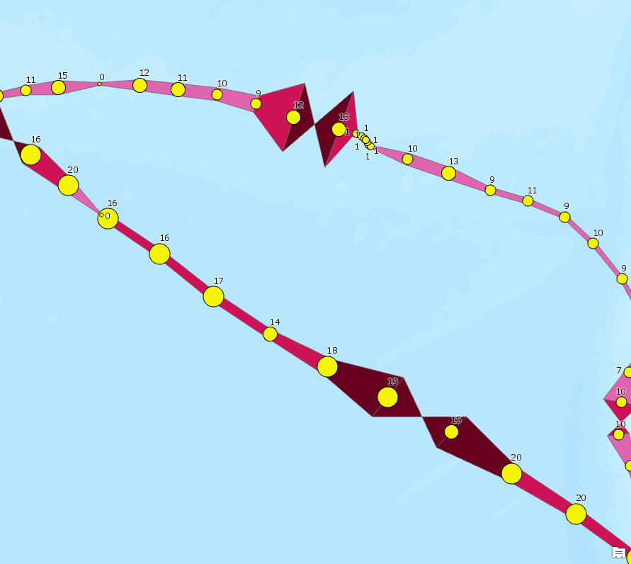
- The taper doesn't seem to always respect the attribute value that determines the width (note data points that have speed label of 17 - Center left of image, are more narrow than those that are 10, 11, 12 - Upper left of image). I suspect somethign is wonky with my equations where I calculate the offsets used to "stretch" the polygon width.
- In addition, for a reason that I cannot pin down, there are some polygons that get turned into "bowties" and become multi-part polygons when they should be quadrilaterals (from troubleshooting it seems like my Insert cursor inserted the 4th coordinate pair before the 3rd?)
If anyone has some tips, suggestions, thoughts, or if this code already exists somewhere. I'd be more than grateful to listen and learn.
Warren
Here's my code as it stands now, I've written it to run from a script tool in ArcGIS Pro (I've also attached the script and toolbox).
# Move bank data source (albatross GPS tracks)
# Dodge S, Bohrer G, Weinzierl R, Davidson SC, Kays R, Douglas D, Cruz S, Han J, Brandes D, Wikelski M (2013)
# The Environmental-Data Automated Track Annotation (Env-DATA) System—linking animal tracks with environmental data.
# Movement Ecology 1:3. doi:10.1186/2051-3933-1-3
# Cruz S, Proaño CB, Anderson D, Huyvaert K, Wikelski M (2013) Data from:
# The Environmental-Data Automated Track Annotation (Env-DATA)
# System: Linking animal tracks with environmental data. Movebank Data Repository. doi:10.5441/001/1.3hp3s250
# imports
import arcpy
from math import sqrt
import sys
from math import cos
# overwrite the outputs
arcpy.env.overwriteOutput = True
# Get parameters from dialog
# input points
source_points = arcpy.GetParameterAsText(0)
# variable parameters
primary_param = arcpy.GetParameterAsText(1) # Parameter to classify and use to "stretch" geometry width
secondary_param = arcpy.GetParameterAsText(2) # Parameter that we'll carry over for symbology purposes
num_breaks = arcpy.GetParameterAsText(3) # Number of classes to break the primary attribute values into
min_width = arcpy.GetParameterAsText(4) # minimum width (metres) that a polygon should be at an end
max_width = arcpy.GetParameterAsText(5) # maximum width (metres) that a polygon should be at an end
break_dictionary = {}
# output polygons
output_polygons = arcpy.GetParameterAsText(6) # output location file gdb
def msg(text):
arcpy.AddMessage(text)
print(text)
def width_factor(attribute_value, dictionary):
for k, v in dictionary.items():
if attribute_value <= dictionary[k][0]:
attribute = k
break
else:
attribute = num_breaks
msg('assigned: {0}'.format(attribute))
return attribute
def offset_calc(distance, plane, latitude):
# https://gis.stackexchange.com/questions/2951/algorithm-for-offsetting-a-latitude-longitude-by-some-a...
if plane == 'y':
offset = float(distance)/111111
offset /= 2
else:
offset = float(distance)/(111111 * cos(latitude))
offset /= 2
return offset
# Understand Attribute Parameter
msg('Understanding attribute parameter...')
value_list = []
with arcpy.da.SearchCursor(in_table=source_points, field_names=primary_param) as parameter_cursor:
msg('Scanning attribute values...')
for row in parameter_cursor:
value_list.append(row[0])
msg('Scan complete.\n\n')
# Assign min/max values
min_attribute = min(value_list)
max_attribute = max(value_list)
msg('Minimum and maximum values assigned: Min({0}), Max({1})'.format(min_attribute, max_attribute))
range_attribute = max_attribute - min_attribute
msg('Range identified: {0}'.format(range_attribute))
step = range_attribute/float(num_breaks)
msg('Range step identified: {0}\n'.format(step))
# Assign polygon width values
width_range = float(max_width) - float(min_width)
width_step = width_range/float(num_breaks)
msg('Assigned width step: {0}'.format(width_step))
# Create dictionary of break values [attribute, width]
for i in range(1, int(num_breaks)+1, 1):
break_value = i * step + min_attribute
width_value = i * width_step + float(min_width)
break_dictionary[i] = [break_value, width_value]
msg('Assigned dictionary break value {0}: {1}'.format(i, break_dictionary[i]))
msg(break_dictionary)
# Create output feature class
workspace_index = output_polygons.rfind('\\')
workspace = output_polygons[:workspace_index]
output_name = output_polygons[workspace_index + 1:]
# Set spatial reference to match input
sr = arcpy.Describe(source_points).spatialReference
msg(str(sr))
msg('Creating "{0}" feature class to store outputs.'.format(output_name))
arcpy.CreateFeatureclass_management(out_path=workspace, out_name=output_name, geometry_type="POLYGON", spatial_reference=sr)
# Add schema
msg('Adding standard fields.')
# Need to have field type detection eventually
arcpy.AddFields_management(in_table=output_polygons, field_description=[
['LINE_FID', 'SHORT'],
['PRIMARY_VALUE', 'DOUBLE'],
['PRIMARY_CLASSED', 'SHORT'],
['SECONDARY_VALUE', 'DOUBLE'],
])
msg('Output feature class created.')
# Open search cursor on points in order to gather geometry
index = 0
feature_dictionary = {}
with arcpy.da.SearchCursor(in_table=source_points, field_names=['OBJECTID', primary_param, secondary_param, 'SHAPE@X', 'SHAPE@Y']) as s_cursor:
for row in s_cursor:
feature_dictionary[index] = [row[0], row[1], row[2], row[3], row[4]]
index += 1
msg('Point features consumed.')
# msg(str(feature_dictionary))
# Puke up features from dictionary
# msg('LAST ITEM: {0}'.format(list(feature_dictionary.keys())[-1]))
with arcpy.da.InsertCursor(in_table=output_polygons, field_names=['LINE_FID', 'PRIMARY_VALUE', 'PRIMARY_CLASSED', 'SECONDARY_VALUE', 'SHAPE@']) as i_cursor:
for key, value in feature_dictionary.items():
msg('KEY: {0}, INDEX: {1}'.format(key, index))
if key == 0:
msg('Process as first point (triangle)')
pass
elif index == int(key + 2):
msg('Process as second last point (triangle)')
pass
elif index == int(key + 1):
msg('Process as last point, therefore skip')
pass
else:
msg('Processing as normal point')
# https://stackoverflow.com/questions/133897/how-do-you-find-a-point-at-a-given-perpendicular-distance...
# msg(str(feature_dictionary[key]))
# Process as usual
# POINT 1
# Get difference of x between prior point and subsequent
# dx = x1 - x2
dx = float(feature_dictionary[key-1][3]) - float(feature_dictionary[key+1][3])
# Get difference of y between prior point and subsequent
# dy = y1 - y2
dy = float(feature_dictionary[key-1][4]) - float(feature_dictionary[key+1][4])
# dist = sqrt(dx*dx + dy*dy)
dist = sqrt(dx * dx + dy * dy)
# Reassign dx and dy
if dx > 0:
dx /= dist
else:
dx = dx
if dy > 0:
dy /= dist
else:
dy = dy
# Get coordinates for starting vertices (counter-clockwise starting top left)
# x3 = x1 + (N/2)*dy
# FACTORED
# Bookmark primary attribute value
wf = width_factor(feature_dictionary[key][1], break_dictionary)
msg('WF: {0}'.format(wf))
# Bookmark break value
bv = break_dictionary[wf][1]
msg('BV: {0}'.format(bv))
x1 = float(feature_dictionary[key][3]) + offset_calc(float(bv), 'x', feature_dictionary[key][4]) * dy
y1 = float(feature_dictionary[key][4]) - offset_calc(float(bv), 'x', feature_dictionary[key][4]) * dx
x2 = float(feature_dictionary[key][3]) - offset_calc(float(bv), 'x', feature_dictionary[key][4]) * dy
y2 = float(feature_dictionary[key][4]) + offset_calc(float(bv), 'x', feature_dictionary[key][4]) * dx
# Get difference of x between prior point and subsequent
dx2 = float(feature_dictionary[key][3]) - float(feature_dictionary[key+2][3])
# Get difference of y between prior point and subsequent
dy2 = float(feature_dictionary[key][4]) - float(feature_dictionary[key+2][4])
dist2 = sqrt(dx2 * dx2 + dy2 * dy2)
# Reassign dx and dy
if dx2 > 0:
dx2 /= dist2
else:
dx2 = dx2
if dy2 > 0:
dy2 /= dist2
else:
dy2 = dy2
# Get coordinates for second pair
# FACTORED
wf = width_factor(feature_dictionary[key+1][1], break_dictionary)
msg('WF2: {0}'.format(wf))
bv = break_dictionary[wf][1]
msg('BV2: {0}'.format(bv))
x3 = float(feature_dictionary[key+1][3]) + offset_calc(float(bv), 'x', feature_dictionary[key+1][4]) * dy2
y3 = float(feature_dictionary[key+1][4]) - offset_calc(float(bv), 'x', feature_dictionary[key+1][4]) * dx2
x4 = float(feature_dictionary[key+1][3]) - offset_calc(float(bv), 'x', feature_dictionary[key+1][4]) * dy2
y4 = float(feature_dictionary[key+1][4]) + offset_calc(float(bv), 'x', feature_dictionary[key+1][4]) * dx2
# Create feature
coordinates = [(float(x1), float(y1)), (float(x2), float(y2)), (float(x4), float(y4)), (float(x3), float(y3))]
try:
msg('Attempting insert')
# 'OBJECTID', primary_param, secondary_param, 'SHAPE@X', 'SHAPE@Y'
# 'LINE_FID', 'PRIMARY_VALUE', 'PRIMARY_CLASSED', 'SECONDARY_VALUE', 'SHAPE@'
data = [feature_dictionary[key][0], feature_dictionary[key][1], width_factor(feature_dictionary[key][1], break_dictionary), feature_dictionary[key][2], coordinates]
msg(data)
i_cursor.insertRow(data)
except:
e = sys.exc_info()[1]
msg('Insert failed: {0}'.format(e.args[0]))Solved! Go to Solution.
Accepted Solutions
- Mark as New
- Bookmark
- Subscribe
- Mute
- Subscribe to RSS Feed
- Permalink
Speaking from a very high level. (It would take me quite some time to understand all the code)
It looks like you calculate the offsets using either the X or Y plane only. I think this could account for the widths looking to be not of relative size as the smaller 17 is almost exactly on the XY axis whose width was then extrapolated using either X or Y only, whereas the larger 11 is almost perfectly on the X axis. (So has ended up with a "correct" relative width)
If the statement above is wrong, please stop reading here!
You could look to create the offset on all axis using code such as (Again very high level, semi pseudo code to give ideas only likely with syntax issues as typed in notepad:
beforePoint = aPointCursorRow
currentPoint = aPointCursorRowWereTurningToAPolygon

dX = current.shape.Centroid.X - beforePoint.shape.Centroid.X
dY = current.shape.Centroid.Y - beforePoint.shape.Centroid.Y

angle = atan2(dX, dY) * 180 / pi

distance = width_factor(current.attributeValue)

newpoint1 = currentPoint.shape.pointFromAngleAndDistance(angle + 90, distance)
newpoint2 = currentPont.shape.pointFromAngleAndDistance(angle + 90, distance)

coordinates = [beforePoint, newpoint1, currentPoint, newpoint2]
**Final Note - You probably would want to use 3 'rows' instead of 2 to make each point.
-possibly substituting currentPoint for nextPoint at the final co-ordinates step.
- calculating the "Angle" using all 3 points, instead of 2 in case the direction chages a lot. (Except for the start and end of the data where you obviously only have 2 points!)
- Mark as New
- Bookmark
- Subscribe
- Mute
- Subscribe to RSS Feed
- Permalink
Luke,
I apologize for leaving you hanging here for almost a year. Real work got in the way of my little side project, but I've recently returned to work on it.
I wanted to let you know that you suggestions and pseudo code were incredibly helpful. Specifically, the calculation to find the angle:
angle = atan2(dX, dY) * 180 / pi
and the use of the pointFromAngleAndDistance method. I had no idea this existed and it was soooooo much easier than how I was attempting to calculate this before.
newpoint1 = currentPoint.shape.pointFromAngleAndDistance(angle + 90, distance)
newpoint2 = currentPont.shape.pointFromAngleAndDistance(angle + 90, distance)
My script now performs how I wanted it to in the first place so thanks for replying and being so helpful!
Warren