Turn on suggestions
Auto-suggest helps you quickly narrow down your search results by suggesting possible matches as you type.
Cancel
- Home
- :
- All Communities
- :
- Products
- :
- Geoprocessing
- :
- Geoprocessing Questions
- :
- Conversion from .kml, global orbits: Arc not treat...
Options
- Subscribe to RSS Feed
- Mark Topic as New
- Mark Topic as Read
- Float this Topic for Current User
- Bookmark
- Subscribe
- Mute
- Printer Friendly Page
Conversion from .kml, global orbits: Arc not treating polar orbiting paths correctly
Subscribe
8906
12
04-07-2014 03:28 PM
04-07-2014
03:28 PM
- Mark as New
- Bookmark
- Subscribe
- Mute
- Subscribe to RSS Feed
- Permalink
Hi all,
Not sure if this is the correct forum for this question/problem, but I couldn't find a strictly projecting category.
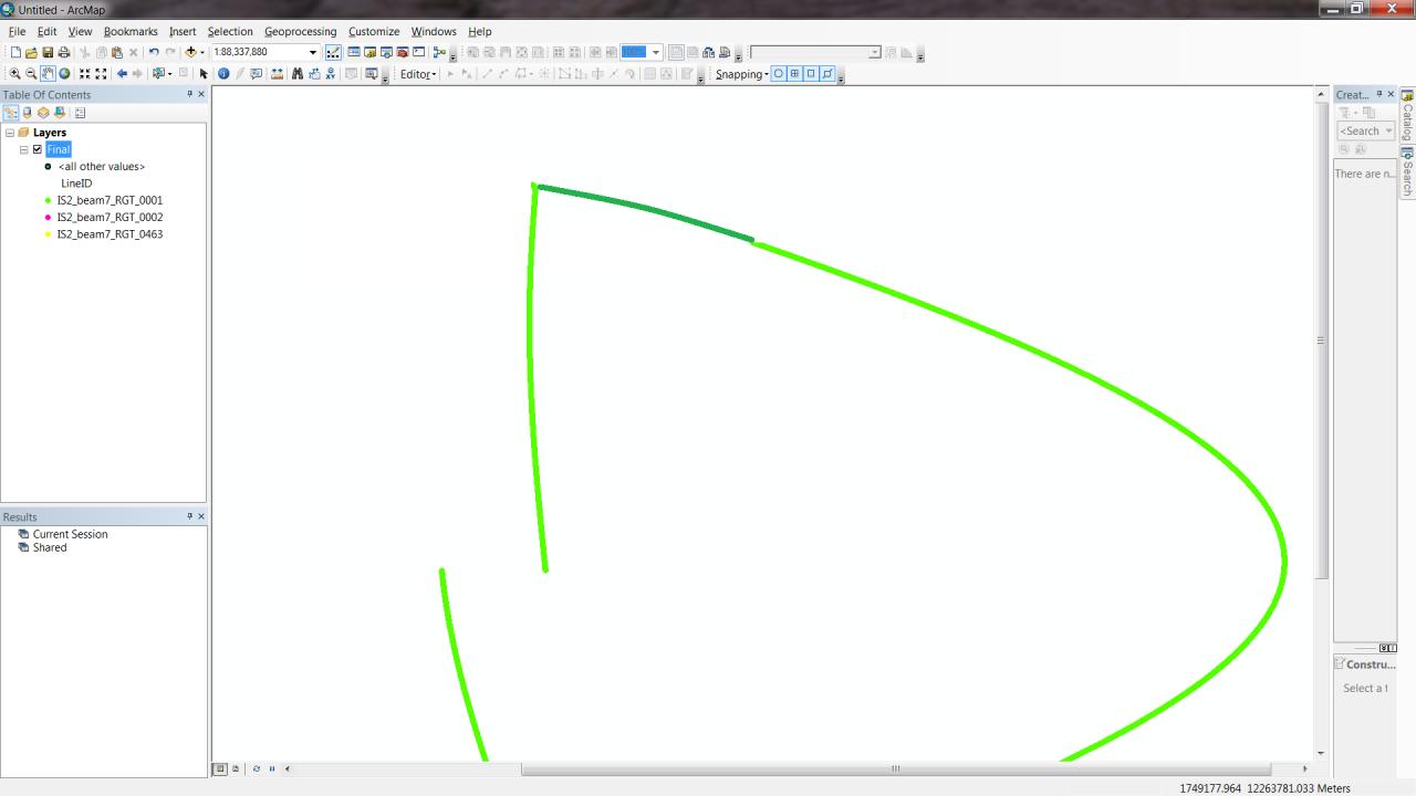
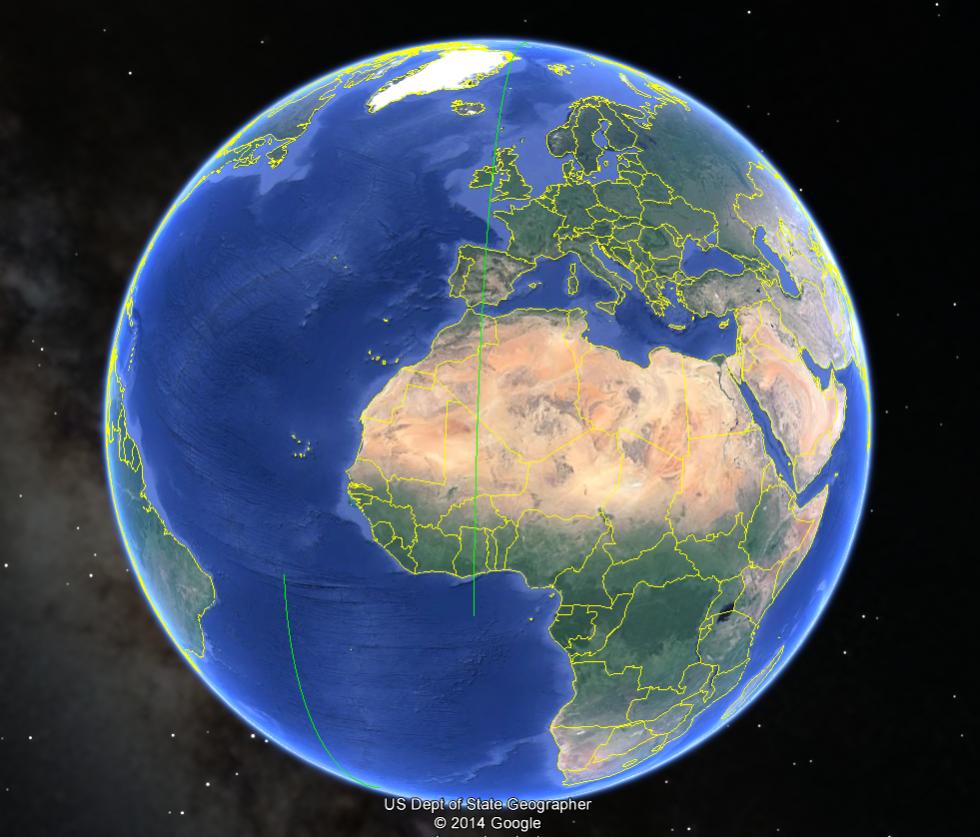
Anyways, I have a few thousand KML files that each have a single polyline, each representing a single satellite orbital path. I am putting them through a script that converts to each file to layer and appends them to one giant gdb, then projects the gdb into Sinusoidal. I'm not quite sure if this is occurring with the conversion to layer/gdb or the projecting (I think it's the conversion), but when it comes time for the orbit to circle around the North pole, it seems that ESRI doesn't know what to do. I've attached a screenshot of what one of the orbits actually looks like, both unprojected (1st image) and in sinusoidal (2nd image), and an edited version of the sinusoidal orbit, according to the way I think it is supposed to look like (3rd image). Additionally, I've attached a screenshot of what the same orbit looks like as it goes around the pole in Google Earth (4th image), since that's the only place I can view KMLs it seems.
Does anyone have any suggestions on how to get around this issue? I need these to be accurate to do some analysis on the paths of the orbits, and the incorrect conversion is going to interfere with that badly. To do the analysis I have to work with shapefiles or geodatabases because there's not much I can do with just the kml in terms of what I need to get done. Manually editing is out of the question as there are thousands of polylines.
Any comments/suggestions/resources would be very helpful.
Thanks a lot
[ATTACH=CONFIG]32892[/ATTACH]
[ATTACH=CONFIG]32893[/ATTACH]
[ATTACH=CONFIG]32894[/ATTACH]
[ATTACH=CONFIG]32895[/ATTACH]
*EDIT: I changed the title to reflect updated problem. Looking at the 1st image, I'm pretty sure the problem is with the conversion and not the projection.
Not sure if this is the correct forum for this question/problem, but I couldn't find a strictly projecting category.
Anyways, I have a few thousand KML files that each have a single polyline, each representing a single satellite orbital path. I am putting them through a script that converts to each file to layer and appends them to one giant gdb, then projects the gdb into Sinusoidal. I'm not quite sure if this is occurring with the conversion to layer/gdb or the projecting (I think it's the conversion), but when it comes time for the orbit to circle around the North pole, it seems that ESRI doesn't know what to do. I've attached a screenshot of what one of the orbits actually looks like, both unprojected (1st image) and in sinusoidal (2nd image), and an edited version of the sinusoidal orbit, according to the way I think it is supposed to look like (3rd image). Additionally, I've attached a screenshot of what the same orbit looks like as it goes around the pole in Google Earth (4th image), since that's the only place I can view KMLs it seems.
Does anyone have any suggestions on how to get around this issue? I need these to be accurate to do some analysis on the paths of the orbits, and the incorrect conversion is going to interfere with that badly. To do the analysis I have to work with shapefiles or geodatabases because there's not much I can do with just the kml in terms of what I need to get done. Manually editing is out of the question as there are thousands of polylines.
Any comments/suggestions/resources would be very helpful.
Thanks a lot
[ATTACH=CONFIG]32892[/ATTACH]
[ATTACH=CONFIG]32893[/ATTACH]
[ATTACH=CONFIG]32894[/ATTACH]
[ATTACH=CONFIG]32895[/ATTACH]
*EDIT: I changed the title to reflect updated problem. Looking at the 1st image, I'm pretty sure the problem is with the conversion and not the projection.
12 Replies
by
Anonymous User
Not applicable
04-10-2014
08:06 AM
- Mark as New
- Bookmark
- Subscribe
- Mute
- Subscribe to RSS Feed
- Permalink
Original User: mwooten3
I'm not claiming you to be slow, or anything of that nature, so I don't know where that came from. I was simply explaining why the way Arc is representing the line is, in fact, problematic.
Yes, the edit should have technically depicted the orbit running along the left side, and not the right side, for the small segment above 75 degrees north. You are correct and it is duly noted. However, the point I was trying to make with the edit is that the orbit does not cut straight across the globe at 75 degrees as depicted, and instead it wraps around the pole, traveling southward along a longitude near that of 180 degrees before making it back to the equator. Still, the edit, albeit off by some bit of longitude for a 15 degree segment, is a lot more correct in its general path than the way Arc illustrates.
Thanks for your suggestion, professor. Trust me, I've heavily considered the option of splitting the line according to where it crosses the 180th meridian, even having written a rough draft of a script to do that very thing. However, after looking more into the problem as a whole, I actually need the line represented as one feature for the other script to work and the analysis to be accurate. It's looking more and more like this is an inherent Arc problem, and an easy fix might not be available. I appreciate you trying to help though.
Yes, I understand that you "need the line to represent the actual path of the satellite".
It is also quite clear that the imaginary part of the line is what you need to eliminate,
and that manual manipulation is not a viable option.
I am not quite so slow as all that.
If you break line where it crosses the meridian you will have three segments:
part 1 of the path
part 2 of the path
and the straight bit across the face of the map.
the straight part should have just two nodes and
the y values of the two ends will be equal and
the x of one end will be at -180 and the other at 180
That should be enough to pick the bad one out of the three automatically.
There are also options for automatically breaking up the original line.
I leave this as a exercise for the student.
I referred to your mistaken assumptions in that your sketch 'corrected' the path
by joining it down the wrong side of the sinusodial shape.
Your 'correction' did not, in fact correct anything: it simply moved the path.
In fact, that path had to start off to the left and then reappear on the right,
not just run down the right limb.
I'm not claiming you to be slow, or anything of that nature, so I don't know where that came from. I was simply explaining why the way Arc is representing the line is, in fact, problematic.
Yes, the edit should have technically depicted the orbit running along the left side, and not the right side, for the small segment above 75 degrees north. You are correct and it is duly noted. However, the point I was trying to make with the edit is that the orbit does not cut straight across the globe at 75 degrees as depicted, and instead it wraps around the pole, traveling southward along a longitude near that of 180 degrees before making it back to the equator. Still, the edit, albeit off by some bit of longitude for a 15 degree segment, is a lot more correct in its general path than the way Arc illustrates.
Thanks for your suggestion, professor. Trust me, I've heavily considered the option of splitting the line according to where it crosses the 180th meridian, even having written a rough draft of a script to do that very thing. However, after looking more into the problem as a whole, I actually need the line represented as one feature for the other script to work and the analysis to be accurate. It's looking more and more like this is an inherent Arc problem, and an easy fix might not be available. I appreciate you trying to help though.
04-10-2014
10:30 AM
- Mark as New
- Bookmark
- Subscribe
- Mute
- Subscribe to RSS Feed
- Permalink
Perhaps making the track a multi-part feature
after you chop out the middle bit.
It should keep the same vertex order, and thus still progress in the right direction...
or you could try a single discontinuous route (Ignore spatial gaps)?
after you chop out the middle bit.
It should keep the same vertex order, and thus still progress in the right direction...
or you could try a single discontinuous route (Ignore spatial gaps)?
by
Anonymous User
Not applicable
04-10-2014
01:07 PM
- Mark as New
- Bookmark
- Subscribe
- Mute
- Subscribe to RSS Feed
- Permalink
Original User: mwooten3
Good suggestion, I'll look into that. Thanks!
Perhaps making the track a multi-part feature
after you chop out the middle bit.
It should keep the same vertex order, and thus still progress in the right direction...
or you could try a single discontinuous route (Ignore spatial gaps)?
Good suggestion, I'll look into that. Thanks!
- « Previous
-
- 1
- 2
- Next »
- « Previous
-
- 1
- 2
- Next »