- Home
- :
- All Communities
- :
- Products
- :
- Geoprocessing
- :
- Geoprocessing Questions
- :
- Buffer, Euclidean vs Geodesic, displaying differen...
- Subscribe to RSS Feed
- Mark Topic as New
- Mark Topic as Read
- Float this Topic for Current User
- Bookmark
- Subscribe
- Mute
- Printer Friendly Page
Buffer, Euclidean vs Geodesic, displaying differently in different projections
- Mark as New
- Bookmark
- Subscribe
- Mute
- Subscribe to RSS Feed
- Permalink
I'm running in circles with this issue. I have a polygon that I am buffering 55m. Originally I buffered it in a UTM projection with the planar algorithm. My map document was in the same projection. A co-worker viewed the buffered file in a map with a geographic coordinate system, and it was in a different place and overlapped an important feature that it does not overlap when the map document is in the UTM projection.
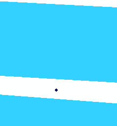 UTM map projection
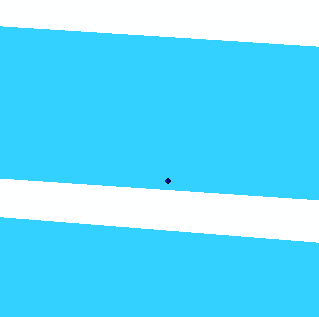 geographic map projection
This polygon covers 2 counties and is pretty long. So I realized I should try doing Geodesic buffering. I projected the polygon to a geographic coordinate system, and buffered it with the geodesic algorithm. In a map in a geographic coordinate system, both the planar and geodesic buffers exactly overlap and display as such, and they overlap the point of interest. However, when the map is in the UTM projection the geodesic buffer stays the same but the UTM buffer, as mentioned, jumps.
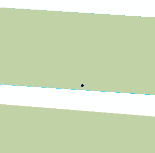 geodesic buffer/geographic map
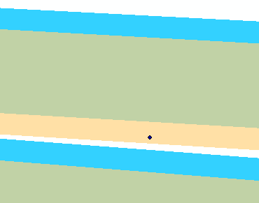 planar/utm
My question is: why does the projected planar buffer jump when moved between a geographic and projected map coordinate system, or why doesn't the geodesic buffer jump? If the geodesic and planar buffers overlap exactly when the map is in a geographic coordinate system projection don't they share lat/lon values, and then shouldn't they skew the same when the map coordinate system changes?
Solved! Go to Solution.
Accepted Solutions
- Mark as New
- Bookmark
- Subscribe
- Mute
- Subscribe to RSS Feed
- Permalink
There are not enough points in the East West direction to properly reflect the shape when converted from one system to another. Have you read the buffer help section and warnings about how the buffer tool works with both types? They actually indicate
Additional information about geodesic buffering
The vertices of input polyline and polygon features are assumed to be connected with geodesic lines (a geodesic line is the shortest path between two points on an ellipsoid). If the intended path between vertices is not meant to follow a geodesic, you first need to explicitly densify the inputs. Geometries can be densified using the Densify tool.
So, if you have a license level above the standard level, consider testing on a backup of the file using the Densify tool.-
- Mark as New
- Bookmark
- Subscribe
- Mute
- Subscribe to RSS Feed
- Permalink
Thank you so much Dan
- Mark as New
- Bookmark
- Subscribe
- Mute
- Subscribe to RSS Feed
- Permalink
Glad it worked Sarah. In my opinion, densifying should be an optional parameter or automatic when a threshold distance relative to the extent is reached