- Home
- :
- All Communities
- :
- Products
- :
- ArcGIS Pro
- :
- ArcGIS Pro Questions
- :
- ArcGIS Pro 2.5: What does the “Source X” and “Sour...
- Subscribe to RSS Feed
- Mark Topic as New
- Mark Topic as Read
- Float this Topic for Current User
- Bookmark
- Subscribe
- Mute
- Printer Friendly Page
ArcGIS Pro 2.5: What does the “Source X” and “Source Y” stored in “control point table” when working with georeferencing refer to?
- Mark as New
- Bookmark
- Subscribe
- Mute
- Subscribe to RSS Feed
- Permalink
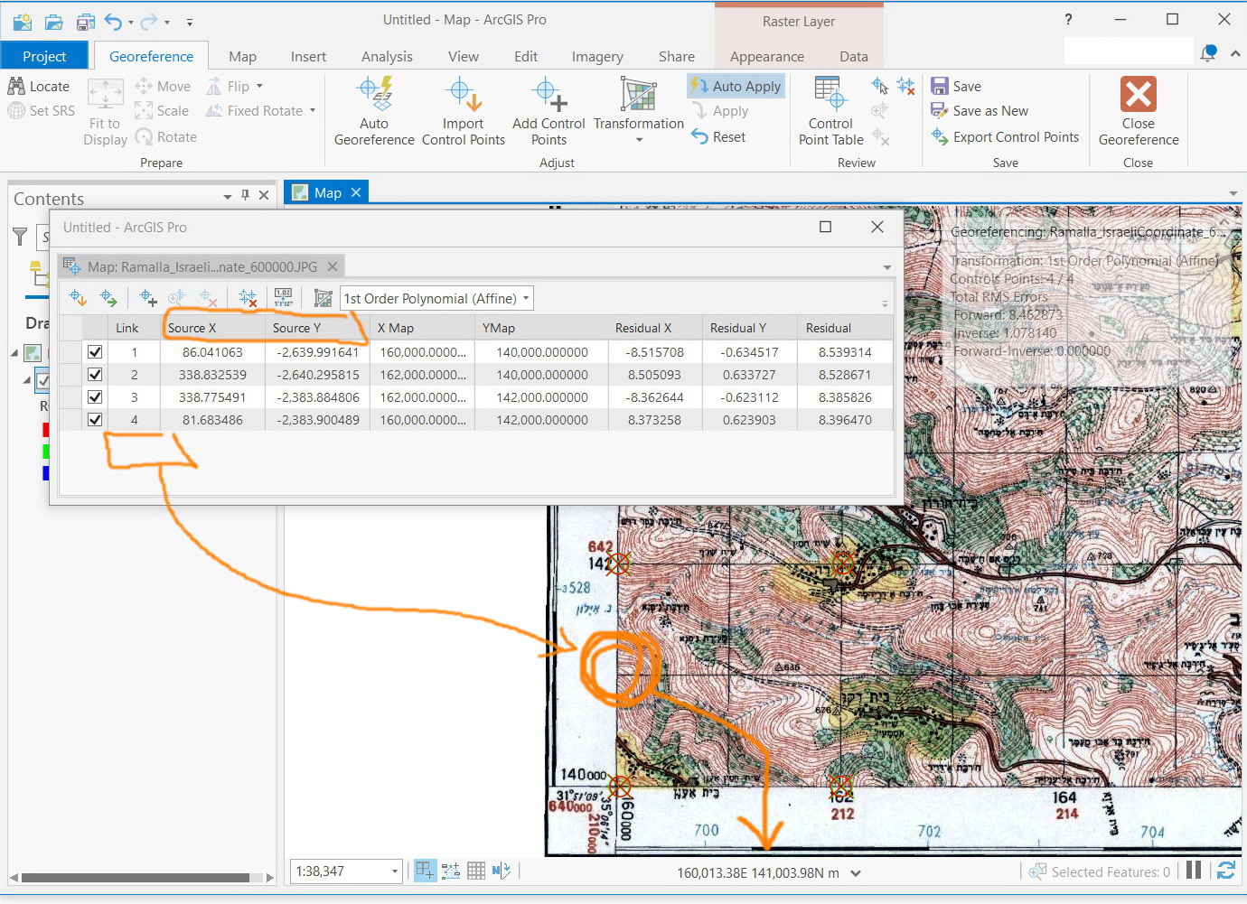
ArcGIS Pro 2.5: What does the “Source X” and “Source Y” stored in “control point table” when working with georeferencing refer to?
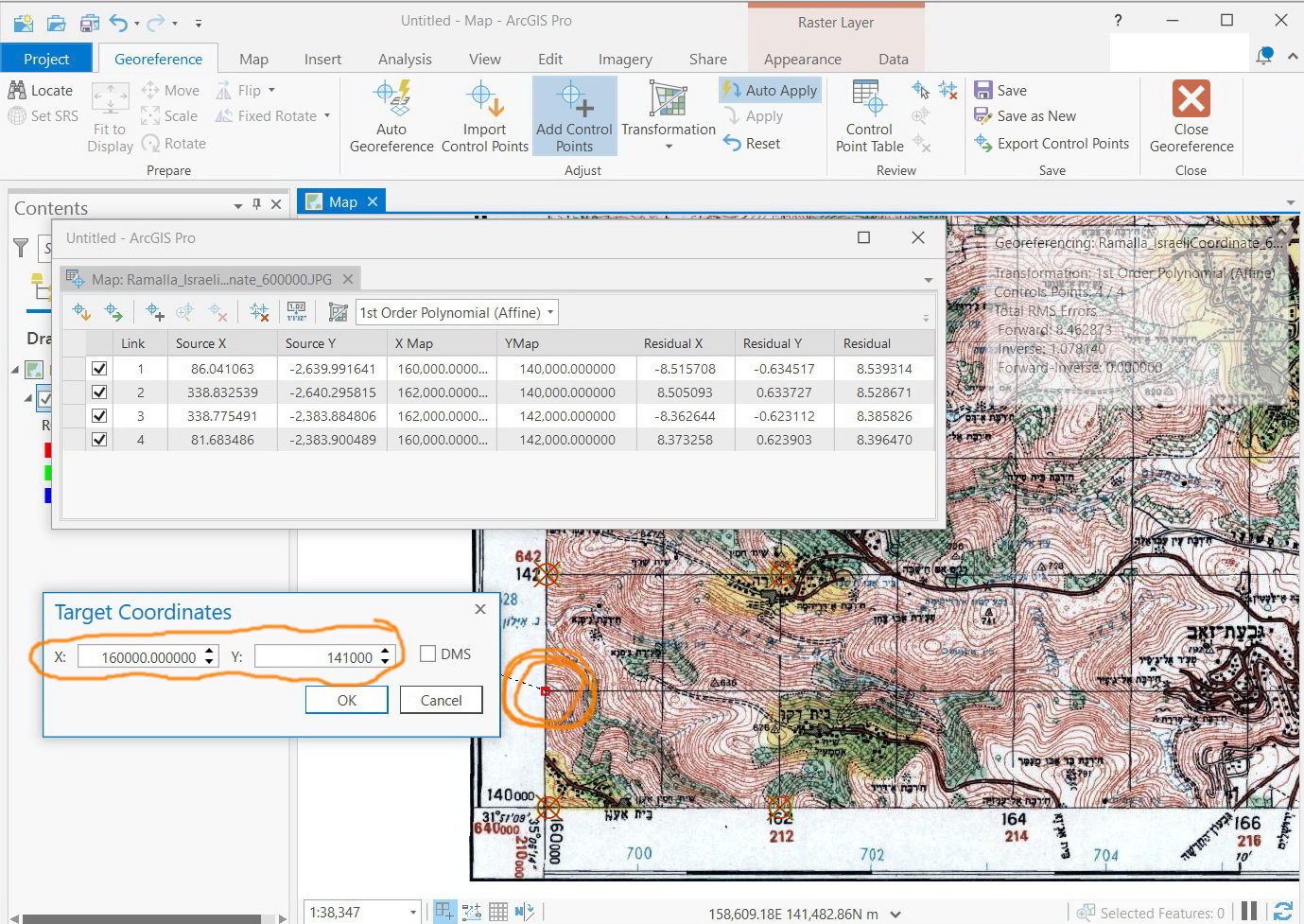
For example, in the screenshot below, I expect that “Source X” and “Source Y” for the marked point will be close to its calculated value (close to 160000 and 140000). However, this appears not the case! The “Source X” and “Source Y” of that marked point appears in the 2nd screenshot.
What could be the interpretation here?
Jamal Numan
Geomolg Geoportal for Spatial Information
Ramallah, West Bank, Palestine
Solved! Go to Solution.
Accepted Solutions
- Mark as New
- Bookmark
- Subscribe
- Mute
- Subscribe to RSS Feed
- Permalink
Hello Mr. Jamal,
The scanned image you have added to the map document view initially would have an unknown spatial reference for it. Firstly, you would assign the coordinate reference system in the map document which would be relevant to the scanned image you have loaded. I could see that you might have used the UTM zone (Projected coordinate system, by units - meter).
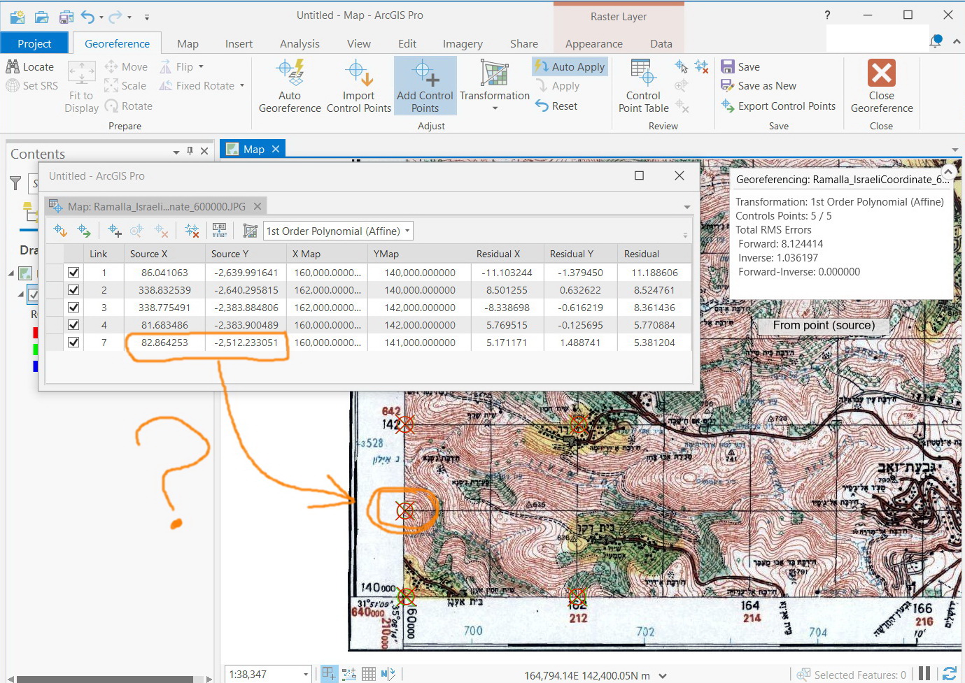
- Each georeference point would have a local point (pixel point or image point as X source, Y source ).
- This would have a corresponding UTM coordinate (X Map, Y Map).
- The interpretation is you would develop a relationship between the (X source, Y source) -> (X Map, Y Map). In other words, what pixel point on the raster would be related to what UTM coordinates in the real world.
- This is done via affine transformation, where you generate two equations between (X source, Y source) and (X Map, Y Map). It would be like X source = a+b X +c Y ; X Map = d + eX + f Y. The difference between a pixel-based position and a relative real-world coordinate produces. If the relation doesn't result in the corresponding like: Y = 2X [if x = 1-> Y = 2*1= 2] and the predicts the relative variation by performing a similar kind of technique (Linear Algebra) which produces a residue (relative position error)
- For better interpretation, I have added a representative image (Hope you got it).
- Mark as New
- Bookmark
- Subscribe
- Mute
- Subscribe to RSS Feed
- Permalink
Hello Mr. Jamal,
The scanned image you have added to the map document view initially would have an unknown spatial reference for it. Firstly, you would assign the coordinate reference system in the map document which would be relevant to the scanned image you have loaded. I could see that you might have used the UTM zone (Projected coordinate system, by units - meter).
- Each georeference point would have a local point (pixel point or image point as X source, Y source ).
- This would have a corresponding UTM coordinate (X Map, Y Map).
- The interpretation is you would develop a relationship between the (X source, Y source) -> (X Map, Y Map). In other words, what pixel point on the raster would be related to what UTM coordinates in the real world.
- This is done via affine transformation, where you generate two equations between (X source, Y source) and (X Map, Y Map). It would be like X source = a+b X +c Y ; X Map = d + eX + f Y. The difference between a pixel-based position and a relative real-world coordinate produces. If the relation doesn't result in the corresponding like: Y = 2X [if x = 1-> Y = 2*1= 2] and the predicts the relative variation by performing a similar kind of technique (Linear Algebra) which produces a residue (relative position error)
- For better interpretation, I have added a representative image (Hope you got it).