Turn on suggestions
Auto-suggest helps you quickly narrow down your search results by suggesting possible matches as you type.
Cancel
- Home
- :
- All Communities
- :
- Products
- :
- ArcGIS Enterprise
- :
- ArcGIS Enterprise Portal Questions
- :
- Re: How to create an upstream semicircle.
Options
- Subscribe to RSS Feed
- Mark Topic as New
- Mark Topic as Read
- Float this Topic for Current User
- Bookmark
- Subscribe
- Mute
- Printer Friendly Page
How to create an upstream semicircle.
Subscribe
4870
4
02-24-2014 02:08 PM
02-24-2014
02:08 PM
- Mark as New
- Bookmark
- Subscribe
- Mute
- Subscribe to RSS Feed
- Permalink
Hi all:
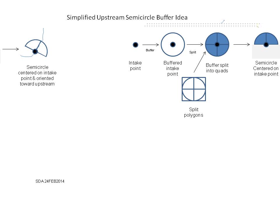
There is likely another method to perfor this task this already so I appreciate any help or ideas offered. I am often asked to find points at a certain distance upstream from a surface water intake. Rather than look at each buffer around each intake manually, I am looking for a method to generate a semicircle of a known radius with its center at the intake and, once generated, align the semicircle's perpendicular radius to the upstream direction in the NHD flowlines. Then a simple select by location can be used.
Right now, I use a set buffer size on the intake points which gives me a conservative distance on the stream. But, I end up looking at each buffer individually so I can identify if the outfall is upstream or downstream. So far this is the method I have explored: 1) generate the buffer around the intake, 2) use the Split Tool to generate four quadrants, 3) delete the bottom half of the semicircle, manually rotate the semicircle tothe upstream direction. I tend to look at upwards of 200 intakes; a simpler or automated method would be great!
I have attached a JPG image with my simplified approach.
4 Replies
02-27-2014
01:00 PM
- Mark as New
- Bookmark
- Subscribe
- Mute
- Subscribe to RSS Feed
- Permalink
There was a recent posting on an ESRI forum about a 'sector analysis' tool. If you can get the bearing of your upstream segment, you might be able to use it to automate some of this process.
http://mappingcenter.esri.com/index.cfm?fa=arcgisResources.modelsScripts
Regards,
Craig
http://mappingcenter.esri.com/index.cfm?fa=arcgisResources.modelsScripts
Regards,
Craig
03-31-2014
11:53 PM
- Mark as New
- Bookmark
- Subscribe
- Mute
- Subscribe to RSS Feed
- Permalink
Each line segment should have a unique ID based upon when it was created (i.e. the first node would have an ID of 1, next 2 etc). This would mean the numbering can be used as an indicator of direction. If you can work out if the line was drawn moving up or downstream you can then select layer by attributes using the ID field being > or < the ID where the intake is located.
Then buffer the selected features using the appropriate buffer specifications.
Not sure how complicated your dataset would be, but that might work for you.
Then buffer the selected features using the appropriate buffer specifications.
Not sure how complicated your dataset would be, but that might work for you.
04-01-2014
04:17 AM
- Mark as New
- Bookmark
- Subscribe
- Mute
- Subscribe to RSS Feed
- Permalink
Just thinking out aloud here.
I'm not aware of any geo-processing object accessible to arcpy that would do what you want. Manipulating geometries in such away would be done via ArcObjects, I would have done this using the ITransform2D interface.
So assuming you are not an ArcObjects bod then I guess you are looking for some sort of model builder approach? Again I'm not aware of any tool that will rotate individual geometries. But there is the rotate tool that will rotate a raster. Why not create a model that takes a single selected semi-circle polygon, convert it into a "mini" raster, run the rotate tool and then convert it back to a polygon.
Whilst this approach should work it would cause your nice semi-circle to pixelate, you may not want to do that?
I think you'll need to get your GIS developer on this, they could easily make a nice addIn button to do this.
04-01-2014
06:35 AM
- Mark as New
- Bookmark
- Subscribe
- Mute
- Subscribe to RSS Feed
- Permalink
If the semi circle is merely symbolical and not used for further analysis, you could use a standard pictorial symbol that respects an angle field for the symbol orientation. Linear Referencing could convert the point to an event on the line network using the Locate Features Along Routes tool. Point events have the option to automatically create an angle field that gives the line tangent or normal angle. That field can be used to orient the symbol. You may need to calculate the angle value into a permanent field while the table is just an event layer, since until the event layer is converted to a feature class the angle field is just an in memory field and not actually stored in the event table. A Reference Scale setting would have to be applied to maintain the symbol at a specific measurable radius size relative to your map scale display. The Linear Reference based angle field may be useful for a ModelBuilder/Python based automation of the process if you must create the semi-circle as an actual feature.
Since it does look like you need to do further analysis, the LR Point Event could still be used to create the angle for the Bearing Distance to Line tool to create the cross hair lines centered on the point at the correct angle relative to your line and the circular buffer to be divided by the cross hair lines. I am sure it is possible with that set of inputs to come up with a few clever selection rules that should be able to eliminate the portion of the semi-circle that you do not want in ModelBuilder. Assuming the Route was oriented in the direction of flow you can use the angle value to distinguish the upstream and downstream portions. A secondary measure filed calculated on the event (take the actual measure and subtract a meter or two) could create a second point event layer that is positioned just enough upstream to select the portion of the circle you want to eliminate in all but he most sharp bends of the river. Only one table event record for the point has to be created to drive all of this.
Since it does look like you need to do further analysis, the LR Point Event could still be used to create the angle for the Bearing Distance to Line tool to create the cross hair lines centered on the point at the correct angle relative to your line and the circular buffer to be divided by the cross hair lines. I am sure it is possible with that set of inputs to come up with a few clever selection rules that should be able to eliminate the portion of the semi-circle that you do not want in ModelBuilder. Assuming the Route was oriented in the direction of flow you can use the angle value to distinguish the upstream and downstream portions. A secondary measure filed calculated on the event (take the actual measure and subtract a meter or two) could create a second point event layer that is positioned just enough upstream to select the portion of the circle you want to eliminate in all but he most sharp bends of the river. Only one table event record for the point has to be created to drive all of this.