- Home
- :
- All Communities
- :
- Products
- :
- ArcGIS CityEngine
- :
- ArcGIS CityEngine Questions
- :
- Re: Streets UV Split Behavior
- Subscribe to RSS Feed
- Mark Topic as New
- Mark Topic as Read
- Float this Topic for Current User
- Bookmark
- Subscribe
- Mute
- Printer Friendly Page
Streets UV Split Behavior
- Mark as New
- Bookmark
- Subscribe
- Mute
- Subscribe to RSS Feed
- Permalink
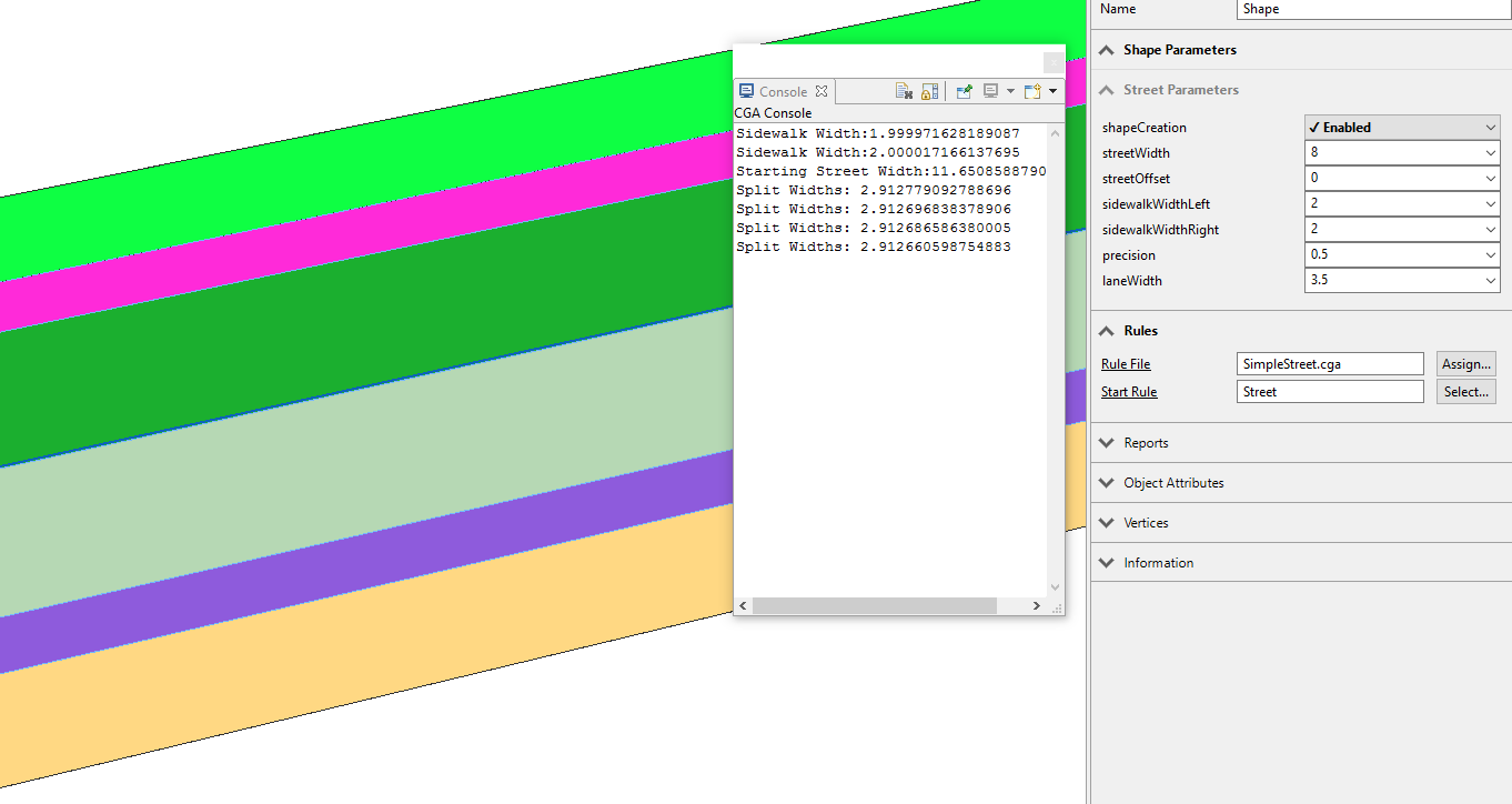
I'm running into something I can't wrap my brain around - I'm trying to split a street shape and it looks as though its adding in 4 extra meters - assuming its because of the default sidewalkWidthLeft and sidewalkWidthRight. This is complicating my splits a bit and when I look through the ESRI rules for streets I can't see where this is being accounted for. Am I missing something? Shouldn't this rule put in 4 equal splits between the sidewalks? The console reports 4 equal splits.
lenAlongV = geometry.dv(0,unitSpace)
##############################
# Street
@StartRule
Street --> print("Starting Street Width:" + lenAlongV) # Print Width
BuildStreet
BuildStreet-->
split(v, unitSpace, 0) {'0.25:RandomColor print("Split Widths: " + lenAlongV)}* # Print Split Widths
RandomColor-->
color(rand(0,1),rand(0,1), rand(0,1))
Sidewalk --> print("Sidewalk Width:" + lenAlongV) # Print Sidewalk Widths
RandomColorInstead I'm getting this
- Mark as New
- Bookmark
- Subscribe
- Mute
- Subscribe to RSS Feed
- Permalink
Hey Devin,
As I read your rule, the street shape should be split along v 4 times, and what is even more interesting is that the dimensions are reading out correctly.
In general, in my experience Street UV Spaces are very weird. I outline some of my own challenges with them in the CS rule documentation.
In the documentation for UV Space Splits it does say the following:
Setting the splitDirectionparameter to unitSpace permits to operate directly on the surface, i.e. work in units (e.g. meters or yards). Depending on the geometry and type of parameterization there is some inherent distortion in this conversion.
Borders (start, end) of the uv split are defined by the minimal and maximal values found in the selected uv coordinates. The genral syntax of the split is the same as in the cartesian case described above, i.e. relative and floating operators (' and ~) can be used as well as the repeat operator (*). Please check out the examples below.
So depending on the street rule, different street rules handle this problem differently. The defaults in Esri.lib use non-unit space UV channels and some clever texturing/math to efficiently and elegantly represent the streets they are designed to represent in units of the shape parameters lane width. This however makes exact dimensions hard to make clear in edits to add things like bike lanes and parking lanes (elements that are hard to represent in terms of street "lanewidth" or in exact units generally). The uvSpace channels are the ones that are likely to not experience distortion however and they tend to be able to generalize to more street shapes than unitSpace.
The complete street rule has many functions in the front of the rule that are used to determine street widths, lane widths, and lane counts at the very beginning of the rule. The Complete Street Rule is using UV channel 0 (unitSpace) like you are in this example to keep everything in exact units, but it only starts V splits after it buffers the main center street section away from the crosswalk/intersection shape.
The results you are seeing I believe are distortion from the fact you're splitting your UV space with Nodes that are set to "Smart". Keep in mind segments that lead to roundabouts or curved spaces are "distorted" UV spaces. What you will notice in the CS rule and likely other street rules is the first thing established is the split u direction UV space that establishes crosswalks (In the case of Street_Modern_Standard.cga, the UV Channels used again are not unitSpace, and are likely to not experience the same distortion you are seeing here). This does more than create a crosswalk+stop bar buffer, it creates a buffer between distortion creating intersections and the street UV space. If you want an example of how this works, in the CS rule you can bend streets and adjust the buffer distance from the crosswalk to the stop bar. Enough distortion and the street rules ability to assess its lane allocation/street geometry just breaks down and you get a mess.
Why does this happen?
I think it is because the intersection shapes can change the minimum and maximal values of the UV texture space so that the street will make splits and other alterations in a distorted UV space (the width of the street is longer at the intersection relative to the rest of the cross-section- see Kristian's Screenshot below for a visual). In fact, the dimensions might be reading out correctly because the street is splitting it the appropriate amount when measured in UV texture space, but once the UV space is distorted what that looks like is a very different matter.
Here is the relevant section of the CS rule Documentation that discusses this issue:
A note on “Space Conflicts”
The issue that comes with this though is that the UVSpace sets 1 and 2 and the unitSpace in set 0 have the potential to have “conflicts”, where generally UV Sets 1 and 2 (Crosswalks) will start eating geometry of UV Set 0 (Main Center Section). The way that this issue was mitigated was by using the space between the crosswalk and the stop bars as “filler” that could be eaten away on angled intersections (intersections that meet at an extreme obtuse or acute angle), without impacting how the street rule functioned. Something to be clear about is that if the crosswalk UVs eat too much geometry, the way the street calculates width and other aspects of the rule might change (harming overall function and stability of the rule). Thus, it might help to increase the spacing between the stop bars and the crosswalk at weird intersections. In most cases though, this problem is something the user does not have to worry about, especially if they are concerned with mainly cross sections.
The solution is to create a crosswalk space or 'buffer' from the intersection or to use only intersections with the cross shape. When I used your code on a different node I got the expected result.

Getting curved streets right is hard based on what I have heard from ESRI CE team. I have frequently described street rules creation as programming on shifting sand. The interactions of the street UVs with other shapes/intersections play a very large role in this. For rule development it always helps to develop rules on a street shape connected to crossings, then try to break the rule on different street shape.
Sorry for the essay, this question is one I revisit from time to time.
- Mark as New
- Bookmark
- Subscribe
- Mute
- Subscribe to RSS Feed
- Permalink
Awesome Dave. Thanks a lot.
I see what you mean - I changed the node to Junction and it works fine. FYI - changing sidewalk widths does absolutely nothing. The behavior is fine I guess, it would be a little easier to code with if the correct units were reporting.
- Mark as New
- Bookmark
- Subscribe
- Mute
- Subscribe to RSS Feed
- Permalink
Yeah if other parameters don't change it, then I think it is the distorted UV space on the street. I was largely just curious.
Sometimes you can't trust the UV units once a distortion happens. I sometimes create a fake inserted cube scoped to the length of the current scope and use it to provide alternate reporting (or just report scope.y/x/z etc). I have tried to develop heuristics with the geometry functions to determine if I could find out if the UV was distorted, and I did not have much success. My best advice is program CGA defensively and assume you need to build your own UV 'foundation'.
If you find any useful functions that might help with detecting a UV distortion I would be interested in knowing about it. I think the challenge is that ideally that distortion could be detected globally before the rule starts to drill further into the shape hierarchy.
- Mark as New
- Bookmark
- Subscribe
- Mute
- Subscribe to RSS Feed
- Permalink
Hello Devin
I know this is an old question, but in case of other people experience the problem I think I found why it happens. Your split is right, and so is what CE is doing, the problem occurs in the way CE is creating the junction between two roads. If you look at the picture below you can see that CE automatically joins the too sidewalks, when this is done the "street" is merged in a rounded corner.
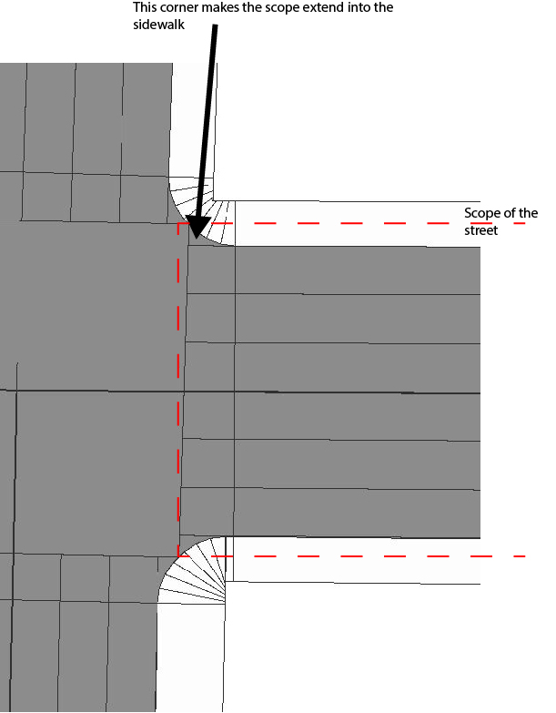
This looks pretty nice but creates a problem when splitting along the street because the scope of the street starts approximately 0.95 meters within the sidewalks. So to work around it can I see two possible methods, either you increase the split closest to the sidewalk by 0.95 meters, or you start by splitting the street across in both ends.
Both of these methods are not perfect, but they will get the job done.
In relation to using the uv split, I find it easier to use the xyz split, and then the first create a alignScopeToGeometry and then afterwards use a rotateScope in case that the "longest" is across the road.
Street -->
alignScopeToGeometry(yUp, any, longest)
rotateScope(0,rotateStreet,0)
Street01
Kind regards
Kristian
- Mark as New
- Bookmark
- Subscribe
- Mute
- Subscribe to RSS Feed
- Permalink
This is what I was referring to when saying the minimum and maximum values change in the texture/geometric space (those at the edge of the intersection where it extends is the new max). This is actually a great graphic explaining where this occurs.
Does this split pattern work with curved streets in your experience? Does it still require a buffer provided by a crosswalk or some other split? I might want to give it a try for the CS rule if it does.
- Mark as New
- Bookmark
- Subscribe
- Mute
- Subscribe to RSS Feed
- Permalink
Unfortunately, it doesn't work on curved streets, and I can't seem to find a workaround. Further is there a problem if a street is divided into multiple segments, then the segments which are not ending in a junction is generated with the "buffer zone", but the scope is not extending beyond the sidewalk leading to problems, of course, this can be fixed with and of/off function. To me, the street functions have lots of potentials, but it is difficult to create a specific design, and as far as I can see in the "complete street" example the CE guys are mainly using clever texturing to create their design.
Have you found a way to evade the scope problem?
- Mark as New
- Bookmark
- Subscribe
- Mute
- Subscribe to RSS Feed
- Permalink
Hi Kristian,
Darn, I was really hoping it might have.
Not past what is not discussed above. The only way I have gotten it to work is by assuming some creation of a "buffer" between the intersection and the street UV (so you have some crosswalk or stop bar spacing that separates the longer/distorted UV at the intersection from the rest). You have to use the UV space however to deal with curves (unitSpace for example).
Beyond this problem is the one of orientation (you can't do speed tables very well for example because something about the alignment changes). Streets as they are very close to being able to do a lot of useful things for conceptual design, but there are gaps in their capabilities. If you have any ideas for this problem, would enjoy your thoughts.
Potential things I have not had time to try include:
- Splitting the street width wise so that the mid-section is as wide as the minimum width in the center of the street (clip off the extract width, send it to asphalt).
- Buffers that adjust width based on distance to the intersection.
For reference, I wrote the complete street example. An updated Repo is here. If you thought I used clever texturing you should take a look at the Standard_Street_Rule...that was way more clever than mine. If you have thoughts on how to make the CS rule more modular or have feature requests please don't hesitate to share them with a Github issue. I really want to be able to do more specific treatments, especially at intersections.
Thanks,
David