- Home
- :
- All Communities
- :
- Products
- :
- ArcGIS CityEngine
- :
- ArcGIS CityEngine Questions
- :
- Custom 3D building models and Procedural Rules
- Subscribe to RSS Feed
- Mark Topic as New
- Mark Topic as Read
- Float this Topic for Current User
- Bookmark
- Subscribe
- Mute
- Printer Friendly Page
Custom 3D building models and Procedural Rules
- Mark as New
- Bookmark
- Subscribe
- Mute
- Subscribe to RSS Feed
- Permalink
Hello everyone
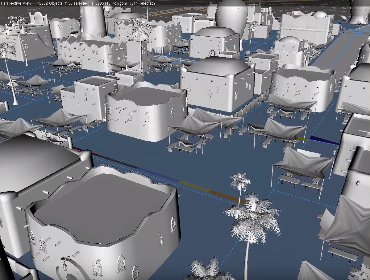
I was watching the presentation by "Walk Disney Animation Studios - Zootopia" today at lunch and couldn’t help but think what a great project that was. Near the end I heard something interesting.
Starting around minute 14 the presenter talks about creating custom 3d buildings (I believe in Maya) and then manipulating them with Procedural rules inside City Engine. In the example he takes one of those custom 3d models and increases/decreases building height, changes the setback etc, all the normal City Engine stuff we know and love.
I know how to create a basic building with .cga rules and thru the inspector manipulate the height field but I don’t know how they go about doing this models imported from another software. Does anyone have any insight into this workflow, or how this can be accomplished?
- Mark as New
- Bookmark
- Subscribe
- Mute
- Subscribe to RSS Feed
- Permalink
After comparing the buildings at 14:06 (before height adjustment) to the buildings at 14:09 (after height adjustment), it seems like the buildings are constructed procedurally in the rules. New floors are added when the height is increased to 30. Assets, like the window decorations, can be inserted in the rules using the i() operation, giving the models more complexity.
However, it is possible to insert models of buildings, but there's a limit to what you can do with them. Changing the height will only stretch the model. But, you can prepare setbacks on a lot and control the location where the building is inserted. This is done in the Instance City Example. (Help -> Download Tutorials and Examples).
- Mark as New
- Bookmark
- Subscribe
- Mute
- Subscribe to RSS Feed
- Permalink
Hello
Thank you Cheryl for replying to my post. I am trying to reproduce the results in the video (organic looking models, First screenshot) and having a difficult time with a few things.
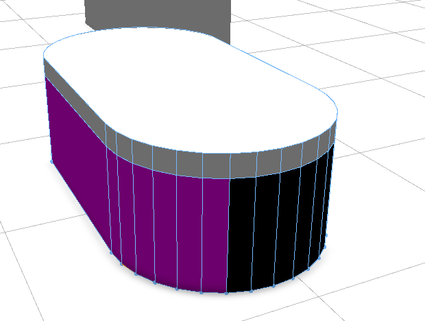
I created an oval building footprint in Blender, exported it as a .OBJ into my CityEngine workspace and created a shape from it. I created a very simple rule to allow for a Height slider and to split the model into a couple parts; Roof, Front and Wall. I dont understand why the faces were split like they did.
Walls are Black and the Front Facade shape is Purple but the proportions of the Side and front shapes are off. Part of the front face is on the side of the model. Can anyone provide some insight on how to resolve this?
Once I have the facades sorted out I would like to try the (i) operation to inset custom .obj models for windows.
The building shapes that are used in the video are much more organic looking, the curves are very nice. All of the models I have created in and for CityEngine have very rigid shapes and harsh corners. Is there an operation to smooth out the model?
version "2017.0"
@Range (5,25)
attr height = 10
@StartRule
Lot -->
extrude(height)
comp (f) {top: Roof | front: Front | side: Wall}
Roof-->
extrude (1)
color(0,0,1)
Wall-->
color(0,0,0)
Front-->
color (1,0,1)
- Mark as New
- Bookmark
- Subscribe
- Mute
- Subscribe to RSS Feed
- Permalink
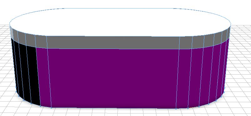
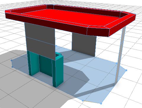
Here is my updated shape...
And I am trying to apply the techniques in Tutorial 6 to it. I am running into a road block when trying to add the floor section. Here is the current .cga code
* File: ParapetHouse.cga
version "2017.0"
/* Attributes *************************************/
window_asset = "/assets/facades/window.obj"
@Range (1,10)
attr height =2
attr groundfloor_height = 1
attr floor_height = 1
attr tile_width = 1
attr Parapet_Inset = .5
attr Parapet_Height = 1
attr ROOF_TYPE = "Parapet"
/* StartRule*************************************/
@StartRule
Lot -->
extrude(height)
comp(f) {front: FrontFacade | side: Wall | top: Roof| back: Back}
Roof -->
ParapetRoof
ParapetRoof -->
offset(-Parapet_Inset)
color(1,0,0)
comp(f) {inside: ParapetBaseFloor | border = ParapetSide}
ParapetSide -->
extrude(Parapet_Height)
FrontFacade -->
split(y){ groundfloor_height : Groundfloor |{ ~floor_height: Floor }* }
Wall -->
split(y){ groundfloor_height: Floor | { ~floor_height: Floor }* }
Groundfloor -->
split(x){ 1: Wall |{ ~tile_width: Tile }* | ~tile_width: EntranceTile | 1: Wall }
EntranceTile -->
split(x){ ~1 : SolidWall | 1 : split(y){ 1: Door | ~1: SolidWall }| ~1 : SolidWall }
Door -->
color(0,1,1)
s('1,'1,0.1)
t(0,0,-0.5)
i("builtin:cube:notex")
SolidWall -->
color(0,1,1)
s('1,'1,0.4)
t(0,0,-0.4)
i("builtin:cube:notex")
Window -->
s('1,'1,0.4)
t(0,0,-0.25)
i(window_asset)
Back-->
color (0,0,1)
split(y){ groundfloor_height : Groundfloor |{ ~floor_height: Floor }* }
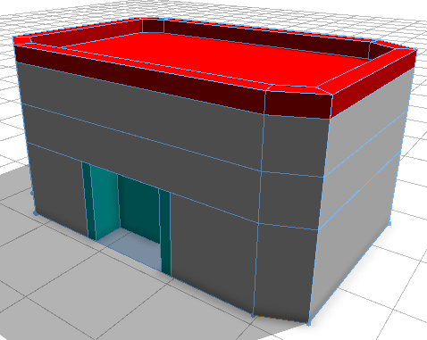
When I try to add the following Floor code, my model breaks and I cant resolve it.
Floor --> split(x){ 1: Wall | { ~tile_width: Tile }* | 1 : Wall }
This is what happens:
I appreciate any advice you can provide.
- Mark as New
- Bookmark
- Subscribe
- Mute
- Subscribe to RSS Feed
- Permalink
Why are the faces resulting from the component split on the oval shaped building not split according to the front and sides of the buildling?
-> The "front" selector in the comp split might not necessarily select the faces that we think would correspond to the front of the building. In the comp split, front is determined by the scope. The scope of your building is determined by the first edge of your oval shaped footprint. When selecting the footprint, the first edge is shown in orange. You can set the first edge manually (select desired first edge -> Shapes -> Set First Edge). If you select the long edge in the front of the oval shaped building and set it to the first edge, you will probably get what you want from the comp split. Here is the reference page for comp(). Take a look at the images in the example called Selectors 1: Quadrant-based. A comp split has been performed on the sphere, and the faces that are categorized as front are red. Also, note that you can examine the scopes of your shapes using the Model Hierarchy (Window -> Show Model Hierarchy -> Inspect Model).
Is there an operation to smooth out the model?
-> No, sorry, there is no operation in cga to smooth a model. You would have to create a model or part of your model in another 3D modeling software such as Maya. Then, you can insert these models into CityEngine using the i() operation.
Why does adding the Floor rule break the model?
-> In the Floor rule, the shapes Wall and Tile are created. In the Wall rule, Floor shapes are created. This creates an endless recursion. You can see this error in the Problems view (Window -> Show Problems): Maximum derivation depth reached. This means that the endless recursion was cut off at some maximum number of recursion levels.
- Mark as New
- Bookmark
- Subscribe
- Mute
- Subscribe to RSS Feed
- Permalink
Once again, Thank you Cheryl! I really appreicate you taking the time to respond to my post.
I think I understand about the component split on the oval shaped building now, I will try when I have access to that workspace this evening, Great!
Is there an operation to smooth out the model?
-> No, sorry, there is no operation in cga to smooth a model. You would have to create a model or part of your model in another 3D modeling software such as Maya. Then, you can insert these models into CityEngine using the i() operation.
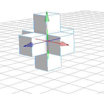
I have been trying to exactly you said in the above comment with no luck. I created this simpleHouse.obj, imported it into my workspace and converted it to shape. When I apply my rule for the height slider; EACH face gets extruded instead of the entire model.


If I import the simpleHouse.obj and apply the rule I get a different, but still wrong result....
Can you please tell me how I can create a basemodel in a 3d modeling program and get the code below to work?
@Range (1,10)
attr height = 2
@StartRule
Lot-->
extrude(height)
So that I can continue making other parts of the model and use the i() operation to put it all together. Once again thanks for your time.
- Mark as New
- Bookmark
- Subscribe
- Mute
- Subscribe to RSS Feed
- Permalink
In the first image, the house is converted to a shape, which means that the initial shape consists of multiple faces, which are all the faces of the house. The rule performs an extrude, so each face in the initial shape is extruded in the normal direction with a distance of 2 set by the attribute height.
In the second image, I'm not really sure how the example was set up, but maybe it looks like the object was inserted but not found so a cube was inserted. Then, the extrude just extruded all six faces in their normal directions.
You can insert the house using i() and then use s() to set the size of the scope to the desired height. This code assumes the initial shape is a 2D shape with the width and depth of the building.
Lot -->
i("simpleHouse.obj")
s('1, height, '1)- Mark as New
- Bookmark
- Subscribe
- Mute
- Subscribe to RSS Feed
- Permalink
Hi,
We're offering coding services for 3d environments. We're fluent in this type of workflow and rendering processes, including VFX and games.
Let me know if we can be of further help. Check out our website.
Regards,
Johnny
------------------------------------------------------------------------------------------------------------------
johnny fehr || junior environment artist
------------------------------------------------------------------------------------------------------------------
vrbn AG – official esri partner || www.vrbn.io || winterthurerstrasse 53 || 8610 uster || switzerland
+41 44 941 90 92 || [email protected] || @vrbnio @JohnnyLiquidcat