Turn on suggestions
Auto-suggest helps you quickly narrow down your search results by suggesting possible matches as you type.
Cancel
- Home
- :
- All Communities
- :
- Developers
- :
- ArcGIS API Silverlight (Retired)
- :
- ArcGIS API Silverlight Questions
- :
- Re: Full extent with polyline graphic crossing the...
Options
- Subscribe to RSS Feed
- Mark Topic as New
- Mark Topic as Read
- Float this Topic for Current User
- Bookmark
- Subscribe
- Mute
- Printer Friendly Page
Full extent with polyline graphic crossing the central meridian
Subscribe
1842
3
12-12-2011 05:42 AM

12-12-2011
05:42 AM
- Mark as New
- Bookmark
- Subscribe
- Mute
- Subscribe to RSS Feed
- Permalink
Hi,
I have a mapping application and basically, I am drawing a polyline going from Australia to North America with several path. I want to be able to zoom to show the entire path, I am doing it this way :
MyMap.ZoomTo(MyLayer.FullExtent.Expand(2));
This is working very well when the path is not crossing the antemeridian, but when I cross it, the full extent gives my the full world. I can understand why but I don't see a way to fix it. Any ideas would be greatly appreciated.
Thanks !
I have a mapping application and basically, I am drawing a polyline going from Australia to North America with several path. I want to be able to zoom to show the entire path, I am doing it this way :
MyMap.ZoomTo(MyLayer.FullExtent.Expand(2));
This is working very well when the path is not crossing the antemeridian, but when I cross it, the full extent gives my the full world. I can understand why but I don't see a way to fix it. Any ideas would be greatly appreciated.
Thanks !
3 Replies


12-12-2011
11:27 PM
- Mark as New
- Bookmark
- Subscribe
- Mute
- Subscribe to RSS Feed
- Permalink
Likely you have to use the 'NormalizeCentralMeridian' method.
When an extent crosses between two frames this method returns a polygon with 2 rings that represent each side of the extent.
There is a sample here .
When an extent crosses between two frames this method returns a polygon with 2 rings that represent each side of the extent.
There is a sample here .
12-19-2011
11:22 PM
- Mark as New
- Bookmark
- Subscribe
- Mute
- Subscribe to RSS Feed
- Permalink
Hi,
Thank you or your answer. But the problem actually come from the NormalizeCentralMeridian method.
If you draw a shape crossing the antemeridian and you get its extent, then you expand it and zoom to it, you will get a nice zoom showing the shape in the middle of the screen.
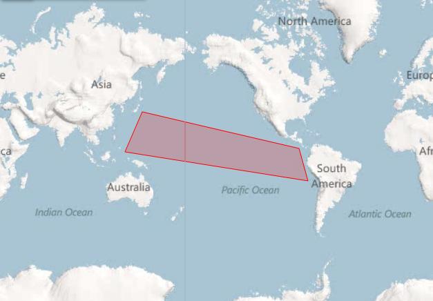
But if for that shape you use the NormalizeCentralMeridian method, the shape will get splitted in two, which is great, but if you get the extent for that shape, it will take the full world. So when you zoom to it you will get a full extent view with one half of the shape on the left and the other half on the right.
Two pictures are better than hundreds of words... 😛
Picture 1 is what i want
Picture 2 is what i get
I thought of merging the two shapes but i could not get it work with all shapes (polygon, lines, rectangle etc...) in a generic and clean way.
Any idea ?
Thank you or your answer. But the problem actually come from the NormalizeCentralMeridian method.
If you draw a shape crossing the antemeridian and you get its extent, then you expand it and zoom to it, you will get a nice zoom showing the shape in the middle of the screen.
But if for that shape you use the NormalizeCentralMeridian method, the shape will get splitted in two, which is great, but if you get the extent for that shape, it will take the full world. So when you zoom to it you will get a full extent view with one half of the shape on the left and the other half on the right.
Two pictures are better than hundreds of words... 😛
Picture 1 is what i want
Picture 2 is what i get
I thought of merging the two shapes but i could not get it work with all shapes (polygon, lines, rectangle etc...) in a generic and clean way.
Any idea ?


12-20-2011
09:40 AM
- Mark as New
- Bookmark
- Subscribe
- Mute
- Subscribe to RSS Feed
- Permalink
This is expected behavior.
You can use the following sample to test. Pan the map and draw the polygon using Add button. Click Zoom to zoom to full extent. Check Normalize and click the graphic to update the geometry. Click zoom to full extent again. Notice that when you update the geometry and the polygon is split in half, the extent changes.
You can use the following sample to test. Pan the map and draw the polygon using Add button. Click Zoom to zoom to full extent. Check Normalize and click the graphic to update the geometry. Click zoom to full extent again. Notice that when you update the geometry and the polygon is split in half, the extent changes.
 <Grid x:Name="LayoutRoot">
  <Grid.Resources>
   <esri:SimpleFillSymbol x:Key="RedFillSymbol" Fill="#66FF0000" BorderBrush="Red" BorderThickness="2" />
   <esri:Editor x:Key="MyEditor" Map="{Binding ElementName=MyMap}" EditCompleted="Editor_EditCompleted"/>
  </Grid.Resources>

  <esri:Map x:Name="MyMap" WrapAround="True" Background="White">
   <esri:ArcGISTiledMapServiceLayer ID="PhysicalTiledLayer"
                                             Url="http://services.arcgisonline.com/ArcGIS/rest/services/NGS_Topo_US_2D/MapServer"/>

   <esri:GraphicsLayer ID="MyGraphicsLayer" MouseLeftButtonDown="GraphicsLayer_MouseLeftButtonDown" />
  </esri:Map>
  <StackPanel  VerticalAlignment="Top" HorizontalAlignment="Center">
   <Button Content="Add" DataContext="{StaticResource MyEditor}"
    Command="{Binding Add}" CommandParameter="{StaticResource RedFillSymbol}"/>
   <Button Content="Zoom" Click="Button_Click"/>
   <CheckBox x:Name="NormalizeGeometry" Content="Normalize" IsChecked="False"/>
  </StackPanel>
 </Grid>
  private void Button_Click(object sender, RoutedEventArgs e)
  {
   var l = MyMap.Layers["MyGraphicsLayer"] as GraphicsLayer;
   MyMap.ZoomTo(l.FullExtent);
  }

  private void Editor_EditCompleted(object sender, Editor.EditEventArgs e)
  {
   if (e.Action == Editor.EditAction.Add)
   {
    foreach (var edit in e.Edits)
     edit.Graphic.Attributes["OriginalGeometry"] = edit.Graphic.Geometry;
   }
  }

  private void GraphicsLayer_MouseLeftButtonDown(object sender, GraphicMouseButtonEventArgs e)
  {
   var originalGeometry = e.Graphic.Attributes["OriginalGeometry"] as Polygon;
   if (NormalizeGeometry.IsChecked.HasValue && NormalizeGeometry.IsChecked.Value)
    e.Graphic.Geometry = Geometry.NormalizeCentralMeridian(originalGeometry);
   else
    e.Graphic.Geometry = originalGeometry;
  }
