Turn on suggestions
Auto-suggest helps you quickly narrow down your search results by suggesting possible matches as you type.
Cancel
- Home
- :
- All Communities
- :
- Products
- :
- Spatial Statistics
- :
- Spatial Statistics Questions
- :
- Re: Breaking Links
Options
- Subscribe to RSS Feed
- Mark Topic as New
- Mark Topic as Read
- Float this Topic for Current User
- Bookmark
- Subscribe
- Mute
- Printer Friendly Page
Breaking Links
Subscribe
3665
3
06-22-2010 02:50 AM
by
Anonymous User
Not applicable
06-22-2010
02:50 AM
- Mark as New
- Bookmark
- Subscribe
- Mute
- Subscribe to RSS Feed
- Permalink
Original User: RajeshMane
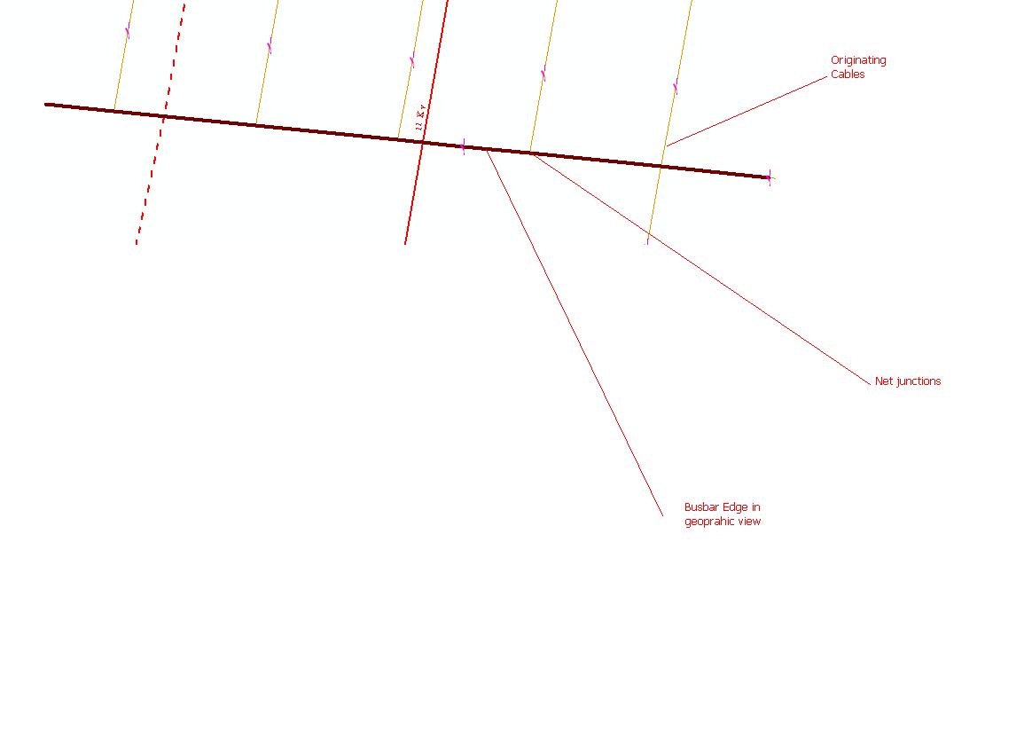
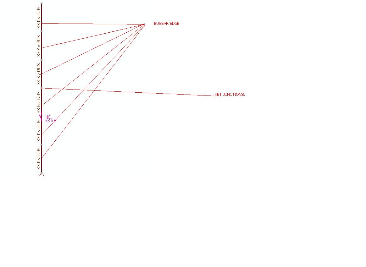
I am using Schematic Desginer 9.3.1. In my geometric network dataset there is a featureclass names Busbar. When i am trying to generate Schematic diagram for selected Busbar(which is only entity but has several vertices from that other cables are orignating. but busbar link is not splitted anwhere its a single complex edge. Cables are originating from edge of busbar and that orignating point complex junciton is present.) It comes in diffrent diffrent schematic elements. I would like know how to avoid this breaking and bring Busbar edge into single schematic element. Since I am using Standard builder diagram type for my Diagram type. please assist.
I have also attached snapshot of those views
3 Replies
06-28-2010
01:13 PM
- Mark as New
- Bookmark
- Subscribe
- Mute
- Subscribe to RSS Feed
- Permalink
Not sure I completely follow the issue but hopefully this helps explain it:
A link in a schematic diagram must connect between 2 nodes. So a link can't just connect to a busbar. So schematics utilizes the net junctions along the busbar for the connections. If you don't want to see the net junctions, you can either set the symbol size to be very small or set the visibility to not visible, but they need to be there for connectivity.
A link in a schematic diagram must connect between 2 nodes. So a link can't just connect to a busbar. So schematics utilizes the net junctions along the busbar for the connections. If you don't want to see the net junctions, you can either set the symbol size to be very small or set the visibility to not visible, but they need to be there for connectivity.
by
Anonymous User
Not applicable
06-29-2010
02:52 AM
- Mark as New
- Bookmark
- Subscribe
- Mute
- Subscribe to RSS Feed
- Permalink
Original User: RajeshMane
thanks Ricks for Quick response,
Actually the issue is, I want Busbar should be one schematic element but it is not coming.Whereas the real view its one feature but has vertexes from that multiple droppers are originating. If I am generating Schematic diagram (using standard builder) based on selection. It shows multiple schematic elements (splits elements on it vertice)which is not correct. Is there any way where It should not break element on it edge vertex. In actual(geographic data there is no break) how can avoid those breaks will be created on sch elements .
07-02-2010
06:12 AM
- Mark as New
- Bookmark
- Subscribe
- Mute
- Subscribe to RSS Feed
- Permalink
Remember that 2 links can't connect directly together...there must be a node at the end of a link. So if there was a complex edge and a 'side' link connected to it, then schematics splits that edge so that the net junction nodes are available to connect the 'side' link. You can run a Node Reduction Rule to get rid of net junctions, just be aware of the side effects. For example, when I use the node reduction rule I normally specify to only remove nodes with 0 or 2 connections. That means get rid of a node if it is an 'orphan' (no connections) or if it is just in the middle of 2 links and has no other connections. Getting rid of 1 connection or > 2 connections is where you have to be careful as the outcome may not be what you want. If you get rid of the 1 connection (node is at the end of a link with no other connections), you will also end up losing the link (as mentioned above a link can't exist without 2 end nodes). If you get rid of > 2 connections, then the connectivity has to be re-calculated and it may not come out exactly the way you think it should. If your network has proper flow in it (i.e. you can trace upstream and downstream), then you can also look at our Node Reduction By Flow Rule which helps with the > 2 case.