- Home
- :
- All Communities
- :
- Developers
- :
- Python
- :
- Python Questions
- :
- Comparing polygons and showing arrowheads along th...
- Subscribe to RSS Feed
- Mark Topic as New
- Mark Topic as Read
- Float this Topic for Current User
- Bookmark
- Subscribe
- Mute
- Printer Friendly Page
Comparing polygons and showing arrowheads along the polygon boundary
- Mark as New
- Bookmark
- Subscribe
- Mute
- Subscribe to RSS Feed
- Permalink
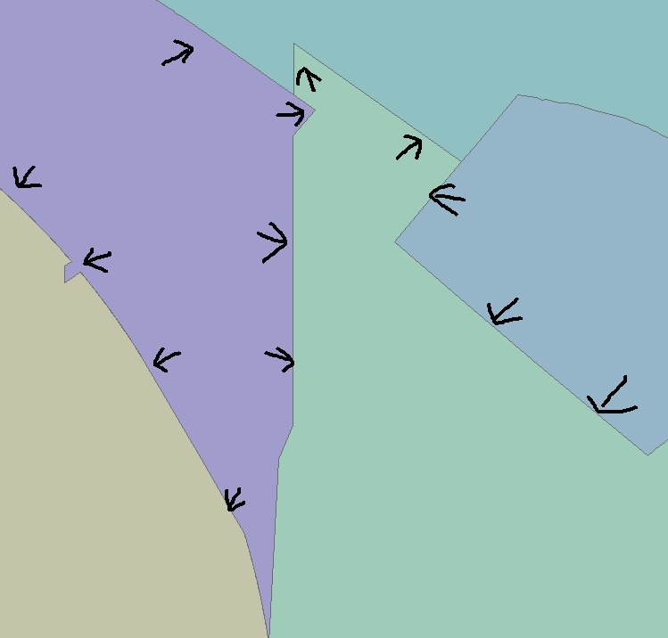
There are no standard visualization tools for this particular purpose. However there is a lot you can do with some Python programming and perhaps representations. First of all you should establish adjacency between polygons and compare the population, next the arrows should be defined. To define those arrows you could pick points on the border of a polygon, determine the bearing of the border at the point and create a line perpendicular to the bearing of the border depending on the populations. This line could be drawn with an arrow head.
I have moved this thread to the Python place.
- Mark as New
- Bookmark
- Subscribe
- Mute
- Subscribe to RSS Feed
- Permalink
I think symbolizing your polygons by population with a fill using a graduated color ramp is the easiest way to visually identify which feature is greater or less than the other.
Could you describe the overall goal here? Maybe there is a different way to approach your problem.
- Mark as New
- Bookmark
- Subscribe
- Mute
- Subscribe to RSS Feed
- Permalink
Depending on how many polygons you have, this semi-manual method may be suitable.
1.) Run Intersect on the polygons as the only input, specifying line as the output type. This creates boundary lines shared between polygons. Unfortunately, there will be two copies of each line, one for each participating polygon.
2.) Dissolve the duplicate lines, turning off create multipart, and unsplit lines. Now you'll have one boundary line between polygons.
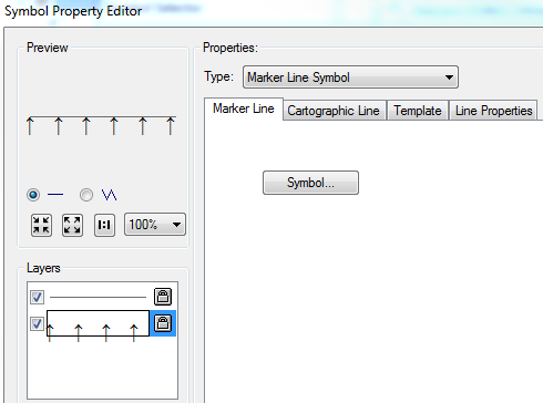
3.) Symbolize the lines as an arrow underneath a line. See below - I added an arrow layer in the line symbology as a character marker symbol from the Arial font (↑).
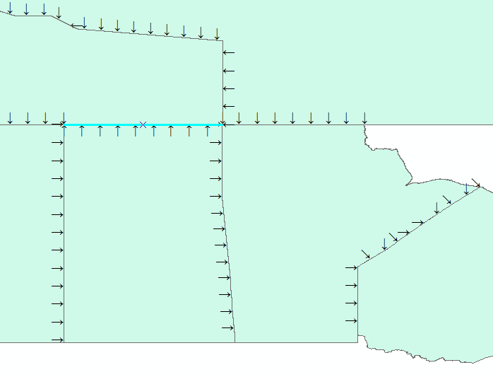
4.) Inspect your lines. They will be symbolized according to the line orientation saved in the shapefile.
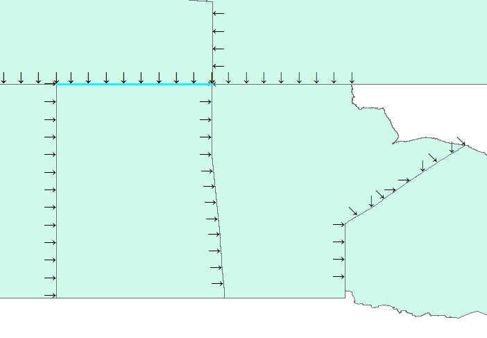
5.) If a line is not symbolized in the orientation you want, start editing, select the line, edit vertices, right-click the line, and choose Flip.
- Mark as New
- Bookmark
- Subscribe
- Mute
- Subscribe to RSS Feed
- Permalink
Hi xander_bakker, blake.terhune, dkwiens,
Sorry for the late reply. I just found out the Geonet has moved my post to
this page. My overall goal is to compare the polygons by the population by
showing arrowhead along the boundaries. In my original shapefile, there
were hundreds of polygons. Because I didn't know how to do it at that time,
so, I ended up doing this manually in Auto cad. I overlaid a grid layer on
the polygons, then placed the arrow heads one by one in each grid, so there
were arrow heads along the polygon's boundaries evenly.
I have done something similar to the xander_bakker's suggestion. The only
problem was our client wanted the arrow head in cad format. I had all those
arrow heads pointing to the boundary perpendicularly in the shapefile.
However, when I converted it to cad, something went wrong and the
orientation of those arrow heads were all messed up. I also tried to save
them as the annotation but it didn't work out during the conversion. So I
had to do it manually instead.
I had suggested blake.terhune suggestion to our client when I first started
on this project, however, they only wanted the arrow heads.
I will try dkwiens suggestion. Thanks for showing me how to remove the
duplicated line. When I was brainstorming this earlier, I thought about
doing something like that, but I couldn't figure out how to remove the
duplicated line at that time. We have to deliver the arrowhead whenever
there is a boundary changed. I will denitely try our your approach.
Thank you so much!