- Home
- :
- All Communities
- :
- Products
- :
- Mapping
- :
- Mapping Questions
- :
- Is it possible to take pre-existing buffers, make ...
- Subscribe to RSS Feed
- Mark Topic as New
- Mark Topic as Read
- Float this Topic for Current User
- Bookmark
- Subscribe
- Mute
- Printer Friendly Page
Is it possible to take pre-existing buffers, make them "flexible", and overlay those buffers onto a topo map, so that the buffer would reflect the contours?
- Mark as New
- Bookmark
- Subscribe
- Mute
- Subscribe to RSS Feed
- Permalink
Some background, so I work for and go to school at West Virginia University and I have been subcontracted to work with the DEP on stream management and analysis for the entire state. My most recent project has been to create buffers around streams leading to surface water intakes in order to help monitor chemical spills and also regulate tanks used by oil and gas companies.
My problem is that when creating the buffers around the streams I failed to include elevation and slope when calculating the distance of the buffers from the stream center (left and right banks for major rivers). My idea is to take the buffers I have (~160 of them) and make them flexible to reflect the topography because 1000 ft linearly looks a lot different than when that same 1000 ft would "decay" because of the topography and slope. I imagine my buffers being able to snap to contour lines to limit the planar length and reflect the topography.
I'm also wondering if using any tools in the 3D analyst would be of use, tools such as 3D length...I'm just not sure.
I'm aware that this could be solved by re delineating these buffers by working out of grid and also using cost-path but I would like to save myself the trouble of having to do these again since the entire project took about 6 months due to tedious calculations and attributions.
Thanks!
I am using Arc Map 10.3 and surrounding software.
- Mark as New
- Bookmark
- Subscribe
- Mute
- Subscribe to RSS Feed
- Permalink
Correct this is an option, but I don't think it's feasible in terms of replication and consistency (also probably not efficient)
- Mark as New
- Bookmark
- Subscribe
- Mute
- Subscribe to RSS Feed
- Permalink
Sorry if I'm missing something obvious in your requirments - but why not just 3D buffer the stream, then intersect that result with a surface model to generate an "effective buffer"?
- Mark as New
- Bookmark
- Subscribe
- Mute
- Subscribe to RSS Feed
- Permalink
Hi Jeff,
I would appreciate it if you could elaborate further on intersecting the 3d buffer with a surface model.The main requirements (parameters):
- 1000 ft buffer on main stem "main portion of water" form the left and right banks
- 500 ft buffer on all tributaries
- 500 ft buffers on all intersecting water-bodies (ponds, reservoirs)
- 1000 ft buffer on lakes
- potential parameter requirement
- account for topography in buffer
There are other parameters concerning the stream's time of travel to the nearest surface water intake, but these aren't in question.
- Mark as New
- Bookmark
- Subscribe
- Mute
- Subscribe to RSS Feed
- Permalink
Hi Shannon-
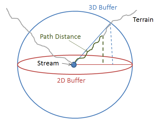
Please see Darren's illustration, it is better than what I could hope to explain using words alone. Now imagine extruding that ring all along the stream into an irregular cylinder - the intersection of this cylinder with the surface would create your 'effective' buffer line. (Not a perfect line, as Darren points out.)
Dan and Darren's suggestion of path distance may be better depending on your data. The resolution of the surface being used would factor in (i.e. a super wide path will give you a distance, but that is only valid somewhere along the path edge). Same thing with vertical measurement - do you measure around every clod of dirt? Every particle of clay? The length would be the same but how it appears will be drastically different.
It's going to be an approximation, no matter what you choose. Good luck with the lawyers 
- Mark as New
- Bookmark
- Subscribe
- Mute
- Subscribe to RSS Feed
- Permalink
Not sure if this helps, but here's how I view the "problem" with using a 3D buffer, looking end-on at a stream. It's still better than a 2D buffer and the smoother the terrain the closer it will be to the true path distance, but still not exactly what's required.
- Mark as New
- Bookmark
- Subscribe
- Mute
- Subscribe to RSS Feed
- Permalink
So to summarize what Darren Wiens is pointing out, Buffer 3D just produces a sphere or cylinder, with no account for the terrain. It is like a regular 2D Buffer in that regard - it is a straight-line radius from the input. As a result, it will produce a larger extent than if it followed the terrain (with the exception of if the terrain was smooth). So it seems like a good idea at first, but unfortunately won't meet the requirements. 
- Generates spheres for point inputs and cylindrical features for line inputs.
ArcGIS Help (10.2, 10.2.1, and 10.2.2)
Chris Donohue, GISP
- Mark as New
- Bookmark
- Subscribe
- Mute
- Subscribe to RSS Feed
- Permalink
Can you convert from a 2D polygon to a TIN? Basically convert it to a bunch of triangle polygons with a Z coord on each point. Of course that would probably stretch out the area of each triangle so that the area of the new polygon would be greater than the original buffer polygon, making it look the same if you looked at it from above. You probably want it to be the same area in the TIN so that the edges of the buffer would take the terrain TIN into account...
I wonder if there's already some code from ESRI that will take a 2D polygon and turn into a TIN and let you set the z coords of the points and it would keep the total area intact by moving the triangles' points where they need to go?
- Mark as New
- Bookmark
- Subscribe
- Mute
- Subscribe to RSS Feed
- Permalink
This is an interesting quandary. I can see future
application up here in Pennsylvania as our booming oil and gas industry mimics West
Virginia’s. It is only a matter of time until our state legislators start
asking us the same questions. I would think that intersecting a 3-D buffer tube
against a DEM or terrain model would have promise. We have a 3.2-foot
bare-earth DEM for the entire state of Pennsylvania.
Shannon, please let me know if you find a solution.
Tom
Thomas G. Whitfield PG (WVU 1974)
Senior Geologist
Pennsylvania Geological Survey
- Mark as New
- Bookmark
- Subscribe
- Mute
- Subscribe to RSS Feed
- Permalink
Just an overall comment:
I'm actually surprised there is not already a tool for this sort of thing. It seems like there would be many uses for a "buffer based on terrain". I almost wonder if a tool to accomplish this already exists, but we are overlooking it.
So that leads to a follow-up question. Who are the spatial guru's at ESRI who we could tap into to find out if such a process exists or can be created?
Chris Donohue, GISP
- Mark as New
- Bookmark
- Subscribe
- Mute
- Subscribe to RSS Feed
- Permalink
Not sure if this is exactly what you need but it looks very close.
Or I could be dead wrong:
Interpolate Polygon To Multipatch (3D Analyst)
Summary
Creates surface-conforming multipatch features from a polygon feature class using a raster, terrain, or TIN surface.
Each polygon feature has its boundary profiled along the surface. Heights are obtained using linear interpolation by sampling at each input vertex and wherever the boundary line intersects surface triangle edges and nodes. This natural densification captures the full definition of the linear surface using a minimal number of samples. Then, all nodes that fall within the polygon are extracted. The nodes are retriangulated in a new memory-based TIN, and the 3D polygon boundary is enforced as a clip polygon. The triangles of this new TIN are then extracted in a series of strips that are used to define a multipatch-based feature.
Usage
- Resulting multipatch will capture the 3D surface representation in its geometry. Planimetric and surface area calculations are included in the output alongside other attributes from the input polygon.
- Consider converting polygons to multipatches if you experience display problems with three-dimensional rendering of polygons draped on a surface.
- The Maximum Triangle Strip Size value must be 3 or larger. This parameter specifies the maximum number of vertices allowed in any triangle strip used in constructing the multipatch. ArcGIS does not have a particular size limit or preference, but some 3D graphic cards might, as triangle strips are directly loaded to the 3D graphics application program interface (API) for rendering. The recommended range is between 128 and 2048.