Turn on suggestions
Auto-suggest helps you quickly narrow down your search results by suggesting possible matches as you type.
Cancel
- Home
- :
- All Communities
- :
- Products
- :
- Mapping
- :
- Mapping Questions
- :
- Re: How to include non network features in Schemat...
Options
- Subscribe to RSS Feed
- Mark Topic as New
- Mark Topic as Read
- Float this Topic for Current User
- Bookmark
- Subscribe
- Mute
- Printer Friendly Page
How to include non network features in Schematic diagram at its proper location
Subscribe
6562
8
06-22-2010 03:14 AM
06-22-2010
03:14 AM
- Mark as New
- Bookmark
- Subscribe
- Mute
- Subscribe to RSS Feed
- Permalink
Hi,
I am usign Schematic designer 9.3.1 , stanadard builder for my schematic diagram. I have tried several ways but failed to bring the point feature which is not participating in Geometric network.
1: I have created new element and assiciated with diagram , when i am trying to generate SCH diagram of selected features(Selection contains both features network/Non network) Network features are properly coming on there schematic location but there is featureclass 'LA' (point feature)which is not participating in Geometric network is still getting its original Geographic location. What is the solution.
2: later I have applied Spatial rule which is searching spatially connected 'LA' from Network edge feature. Still the same.Its on geographic location which is not suppoesed to be correct.
3: I have used Reverse relation which is pulling the 'LA' near to its corresponding edge feature(centroid of line) but not on proper location. Snapshot attached.
Can Anyone help me out to bring the nonnetwork feature on it proper sch location.
8 Replies
06-25-2010
07:10 AM
- Mark as New
- Bookmark
- Subscribe
- Mute
- Subscribe to RSS Feed
- Permalink
When you are doing the initial configuration in schematic designer, just right click the diagram type and choose to import feature classes/tables. Point to the feature class you want and it will be imported. Done. A user in the map can select a feature from that class and generate a diagram with it. When using rules (spatial or relationship), the relate option is important. If you check relate, it tries to create a parent/child type of concept which is normally used to draw a parent container around the children. It sounds like your case is simple and therefore you should not check the relate box and potentially you don't need rules at all. Just import the feature class.
06-28-2010
05:00 AM
- Mark as New
- Bookmark
- Subscribe
- Mute
- Subscribe to RSS Feed
- Permalink
Thanks Rick,
I have tried what you have explained. But the still LA feature is coming only on its geographic location and other features are coming properly as per sch location. It seems It is because 'LA featureclass is not part of geometric network. I would request kindly suggest if any other workaround which I can implement over on it.
I have tried what you have explained. But the still LA feature is coming only on its geographic location and other features are coming properly as per sch location. It seems It is because 'LA featureclass is not part of geometric network. I would request kindly suggest if any other workaround which I can implement over on it.
06-28-2010
12:49 PM
- Mark as New
- Bookmark
- Subscribe
- Mute
- Subscribe to RSS Feed
- Permalink
So I am not completely following what you are trying to do. You said "LA feature is coming only on its geographic location and other features are coming properly as per sch location". What determines sch location vs geographic location for you? Initially, unless you set a layout algorithm to be automatically applied for your diagram template, all nodes come in the initial geographic position and the links are simplified (no vertices). So are you telling the system to automatically apply an algorithm at the diagram type level?
Since you are adding things that are not 'physically' connected to the geometric network, the system will add them as 'orphan' nodes. Orphan nodes don't move (or in some cases only slightly move) when an algorithm is applied because they are not part of the connectivity. If you want them to be 'logically' connected, then you need to have the system create links during the spatial query rule.
The rule properties that you are using show using the relate option. Relate options are only useful when trying to create parent/child effects with a container. So the container is an object that contains children. If the children move, the container dynamically resizes. If the container moves, the children move relative to the container.
It sounds like you should not be using Relate option first of all. It seems like you should be using the create links option. One issue with that is that a link needs to connect to 2 nodes. It seems like you are adding nodes based on proximity to a link (busbar), so that won't work as you can't connect a link from a node (LA) to a link (busbar). So you may need to modify that rule so that you get the LA's based on some point feature that is always found on or near the BusBar, then you can use the create links option. If links are created, then the LA objects are 'connected' and therefore any algorithm will properly move the LA nodes (i.e. they are no longer 'orphan').
We also have a relationship rule. So if there happens to be a relationship class from those LA objects to other geometric network objects, that could be another way to add them.
Final thing I noticed is that you currently have the LA set as the source and Busbar as the target. That might be correct, but just making sure. Normally the 'source' is something you know the user will select. Typically that is something in the geometric network. Then you are saying that based on something in the source being selected, automatically have the system add something from the target whether the user selected it or not. So maybe I am wrong here, but it seems like you would want busbar as the source and LA as the target, but I don't know the use case here.
Rick
07-01-2010
04:52 AM
- Mark as New
- Bookmark
- Subscribe
- Mute
- Subscribe to RSS Feed
- Permalink
Thanks Rick for your quick response.
Actually there is no relation in busnar and LA featureclass. Only thing is LA always comes at one end of busbar.
I request you to please eloborate more on your this solution given below on proper steps.
"sounds like you should not be using Relate option first of all. It seems like you should be using the create links option. One issue with that is that a link needs to connect to 2 nodes. It seems like you are adding nodes based on proximity to a link (busbar), so that won't work as you can't connect a link from a node (LA) to a link (busbar). So you may need to modify that rule so that you get the LA's based on some point feature that is always found on or near the BusBar, then you can use the create links option. If links are created, then the LA objects are 'connected' and therefore any algorithm will properly move the LA nodes (i.e. they are no longer 'orphan')
07-01-2010
11:45 AM
- Mark as New
- Bookmark
- Subscribe
- Mute
- Subscribe to RSS Feed
- Permalink
So this totally depends on your data model. Remember that a link must connect to 2 nodes. So if your 'LA' objects are always within some distance of then end of a BusBar, we are close. The next question is: What objects are at the end of busbar's? Are they always net junctions or some other type of feature? Is it consistent.
Assuming that there is a consistent case, we need to get to some statement like: 'LA' objects are always connected to NetJunctions that appear at the end of a busbar and to figure out which end is simply based on the spatial distance of .005.
Now with that statement it is pretty easy to setup in the system. Several ways to do this, but here is one way I can quickly think of:
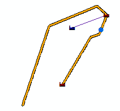
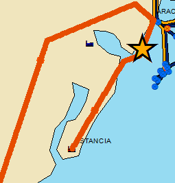
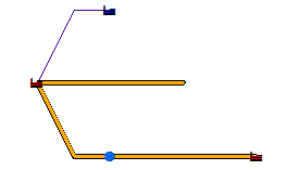
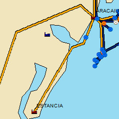
See the attached pictures. On the 'map' image, you see 2 gas plants (Red) and 1 electric plant (blue). The electric plant is not part of the geometric network. I am using a spatial rule from the gas plants (I know the user will select those) to get any electric plants within .22 decimal degrees and add them to the map and connect to the gas plant via my new link element type. The 'mapselection' image shows what is selected. Notice that the electric plant is not part of the selection. The 'initialdiagram' image shows the initial diagram generated. You can see that the spatial rule has run and a new 'logical' link has been created between the electric plant and one of the gas plants based on the spatial rule criteria. The 'diagramwalgo' image shows applying an algorithm and here you see that the electric plant properly moves because it is logically connected to the rest of the network.
Assuming that there is a consistent case, we need to get to some statement like: 'LA' objects are always connected to NetJunctions that appear at the end of a busbar and to figure out which end is simply based on the spatial distance of .005.
Now with that statement it is pretty easy to setup in the system. Several ways to do this, but here is one way I can quickly think of:
- Use the Designer application to edit your schematic dataset
- Create a new link element type and associate it to your diagram type (this will be used to represent this 'logical' link that the rule will create)
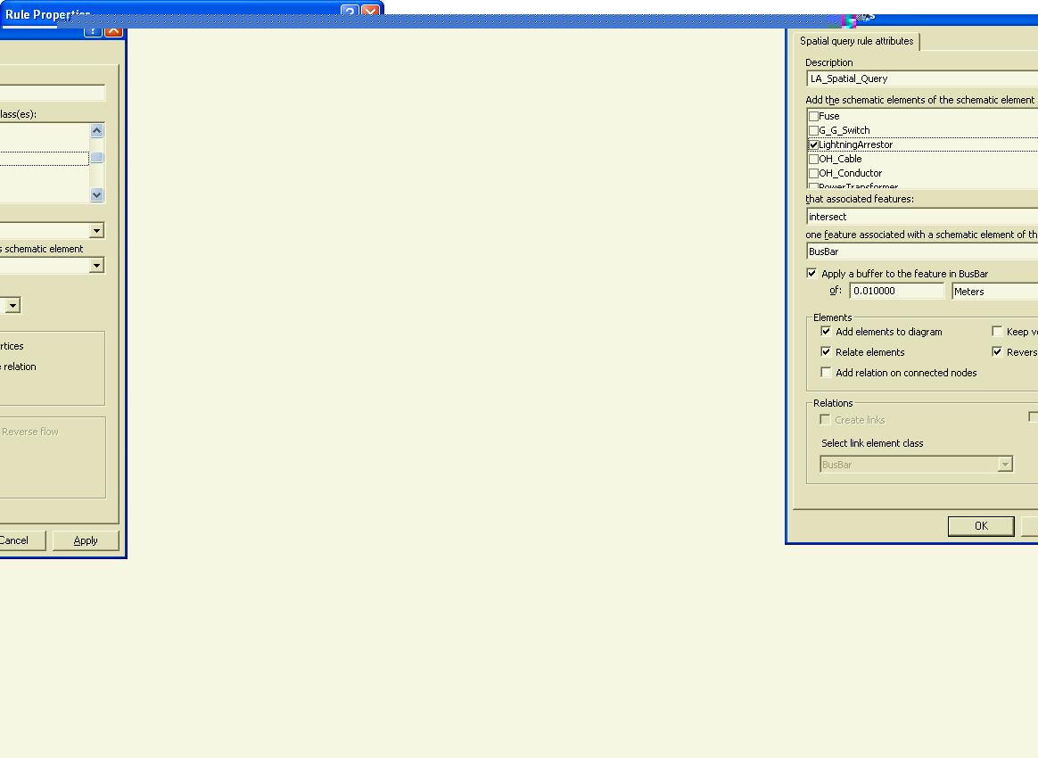
- Create (or modify existing if it exists) the spatial query rule. Make sure not to check the Relates box. Check the box for Create Links and use the dropdown to select the link element type you created in the previous step.
See the attached pictures. On the 'map' image, you see 2 gas plants (Red) and 1 electric plant (blue). The electric plant is not part of the geometric network. I am using a spatial rule from the gas plants (I know the user will select those) to get any electric plants within .22 decimal degrees and add them to the map and connect to the gas plant via my new link element type. The 'mapselection' image shows what is selected. Notice that the electric plant is not part of the selection. The 'initialdiagram' image shows the initial diagram generated. You can see that the spatial rule has run and a new 'logical' link has been created between the electric plant and one of the gas plants based on the spatial rule criteria. The 'diagramwalgo' image shows applying an algorithm and here you see that the electric plant properly moves because it is logically connected to the rest of the network.
07-02-2010
05:16 AM
- Mark as New
- Bookmark
- Subscribe
- Mute
- Subscribe to RSS Feed
- Permalink
Thanks Rick for quick response. Bypass node worked in this case. but when I have applied crossing then crossing symbol did not placed on intersection of the link. how to place crossing in this case.
I have done maximum things through configuration level. Is that possible find overlaps at diagram generation level and use bypass node. If crossing doesnt work I dont mind. But it should bypass the nodes
I have done maximum things through configuration level. Is that possible find overlaps at diagram generation level and use bypass node. If crossing doesnt work I dont mind. But it should bypass the nodes
07-02-2010
05:26 AM
- Mark as New
- Bookmark
- Subscribe
- Mute
- Subscribe to RSS Feed
- Permalink
Sorry Rick,
Request you to ignore my last reply for this thread. regarding 'LA' Feature I have tried steps which you have explained. But new link element was not placed also LA was not shown on its location. Could you please tell me The new link which I am supposed to create does Extrimitynode and originnode and UCID, UOID attribues needs to be created. Please assist.
Request you to ignore my last reply for this thread. regarding 'LA' Feature I have tried steps which you have explained. But new link element was not placed also LA was not shown on its location. Could you please tell me The new link which I am supposed to create does Extrimitynode and originnode and UCID, UOID attribues needs to be created. Please assist.
07-02-2010
05:55 AM
- Mark as New
- Bookmark
- Subscribe
- Mute
- Subscribe to RSS Feed
- Permalink
Thanks Rick,
For your support and quick response. We appreciate your knowledge sharing.
i have tried the steps which you have shown. It worked well. Once again thanks.
For your support and quick response. We appreciate your knowledge sharing.
i have tried the steps which you have shown. It worked well. Once again thanks.