Turn on suggestions
Auto-suggest helps you quickly narrow down your search results by suggesting possible matches as you type.
Cancel
- Home
- :
- All Communities
- :
- Products
- :
- Data Management
- :
- Data Management Questions
- :
- Is there a way to stretch a polygon?
Options
- Subscribe to RSS Feed
- Mark Topic as New
- Mark Topic as Read
- Float this Topic for Current User
- Bookmark
- Subscribe
- Mute
- Printer Friendly Page
Is there a way to stretch a polygon?
Subscribe
11774
11
10-06-2011 01:02 AM
10-06-2011
01:02 AM
- Mark as New
- Bookmark
- Subscribe
- Mute
- Subscribe to RSS Feed
- Permalink
As the title says, I wish to stretch an insanely huge and complex polygon a certain distance X and Y along a constant slope.
One solution would be to move the polygon every 0.001 distance increment, and then perform a merge, but I would rather like to avoid this method... due to distance involved and, I can't just select 2 vertices on one side and move them a set X Y distance due to the millions of vertices involved.
A visual example, The US Great Lakes, as one polygon. I want to stretch that polygon from it's current location, to the south and west (225* azimuth), by a distance of 500 miles. I can move it, but that just gives me 2 polygons, I need all the space in between the orig polygon and the moved polygon to be included.
Another..
_
(_) is my polygon...
I want to stretch it 5 spaces east...
______
(______)
and get something that looks like that as a result
How do I accomplish this?
Thanks
11 Replies
by
Anonymous User
Not applicable
10-06-2011
09:32 AM
- Mark as New
- Bookmark
- Subscribe
- Mute
- Subscribe to RSS Feed
- Permalink
Ryan,
If your using ArcGIS 10, you can do this relatively easily.
Edit the vertices of the polygon you wish to stretch then select the vertices (drag a box) down the side of the polygon you wish to stretch. Hover over the selected vertices, right click and select 'move'. Enter the x,y distance you wish these vertices to move.
If you're stretching to a cardinal point then one of these will be 0. If you're moving a distance and direction then you can do some 'simple trigonometry' to work out what the delta x and y will be.
10-06-2011
10:57 AM
- Mark as New
- Bookmark
- Subscribe
- Mute
- Subscribe to RSS Feed
- Permalink
Ryan,
If your using ArcGIS 10, you can do this relatively easily.
Edit the vertices of the polygon you wish to stretch then select the vertices (drag a box) down the side of the polygon you wish to stretch.
Thanks for the reply,
However, as I mentioned, there are a lot, more like 100+ million vertices, so I can't just drag a box because the polygon is so complex. Imagine one polygon of the Great Lakes edge at a spatial resolution of 1m... there are so many inlets, outlets, small tiny islands just off the shoreline that also are part of the polygon etc, it would take me years to manually select nodes.
I was thinking I could...
1) create a 'planar' DEM of 0 elev that encompasses my polygon and the area surrounding it
2) convert my complex polygon to a raster (if my comp has enough memory to actually do this!)
3) convert the raster to grid or something/someway with a false elevation (lets say 400ft)
3) add the grid to the DEM to create a new DEM.
so, a cross-section of my new DEM will look like this ___----__--___--_ , the base DEM being the surface and the polygon being raised a set elevation
4) create a hillshade at the proper Angle and Az, which will 'stretch' the polygon
5) nominalize the hillshade data (0 for no shade 1 for shade, as I remember hillshades giving a value from 0-255?)
5) combine that hillshade with the raster
6) convert that combined raster to polygon.
but that seems like a lot of work...as it's based on my limited exposure to ArcMap, so the steps may not be correct as I don't know a lot about creating elevation models, grids etc.
Another real-world example would be, to show the movement of a glacier, which is represented by a complex polygon covering thousands of square km, at 1m spatial resolution, so the edge has intricate nooks, crannies, doubles back on itself, has detached pieces that you still want to show movement etc. How do you stretch that entire glacier polygon 0.5m at an Az of 10deg? I need the resulting polygon to encompass movement of the glacier to include every square centimeter it moves across, not just the beginning and end.
Ryan
10-06-2011
04:10 PM
- Mark as New
- Bookmark
- Subscribe
- Mute
- Subscribe to RSS Feed
- Permalink
It sounds like what you want is very similar to the convex hull of the initial and final polygons. You may be able to take the convex hull, which should be a relatively simpler geometry, and cut off the parts that obscure the concavities of the input geometries (essentially the end caps) and then merge them all together... Would that approach work?
10-06-2011
05:25 PM
- Mark as New
- Bookmark
- Subscribe
- Mute
- Subscribe to RSS Feed
- Permalink
An interesting task made harder by having too many vertices in a polygon.
100m vertices, are you serious?? The first thing I would do is DICE the glacier up for performance and sanity.
Have you considered using rubber sheeting? Now called Spatial Adjustment.
0 Just add a few links to show how much distortion you require and run Adjust.
You would add long links at the tongue and short links at the top.
Put some identity links at the far end to anchor it.
Save your links to enable you to repeat and illustrate.
If you need more points than can be added by hand:
1. Make up some from - to points with paired IDs.
This may come from a grid of points that you systematically move with some sort of equation.
2 Convert this to a tab separated text file to load into the Adjust tool
3 Run the adjust.
You could turn the from to pairs into a set of vectors to check the distortion is as required.
The limit in ArcIINFO Workstation was 50,000 links. It may be a lot less in ArcMap, but you don't need a vector for every vertex. Adjust automatically builds two TIN of the distortion in x and y and applies it to each glacier vertex.
10-06-2011
07:29 PM
- Mark as New
- Bookmark
- Subscribe
- Mute
- Subscribe to RSS Feed
- Permalink
It sounds like what you want is very similar to the convex hull of the initial and final polygons. You may be able to take the convex hull, which should be a relatively simpler geometry, and cut off the parts that obscure the concavities of the input geometries (essentially the end caps) and then merge them all together... Would that approach work?
in essence, If I were able to select all vertices that comprise lines that create convex at a specified azimuth, and then are able to stretch those points a specified distance along that azimuth, creating new polylines between the orig location and new location and convert those polylines back to polygon....maybe?
Hrm. so I clipped 150 polygons out of the 1M+ polygons to test on.
I tried using Cartography Tools -> Masking Tools-> Feature Outline Mask. That resulted in the creation of a polygon the exact shape but slightly larger than my selected polygon. The result looks like the Buffer Tool. Mask was set to CONVEX_HULL, but greyd out, unchangeable.
I tried X-Tools Convex Hull Tool, and it gave me one huge polygon, basically a square, that encompassed my polygons. Neither results were anywhere near helpful
It's not like these tools have a lot of options to screw up.. input, output, projection/scale and buffer size. I was expecting it to ask me for an azimuth to calculate which verticies of the polygon create lines that are convex to the azimuth.
Do I need to convert these polygons to polylines first?
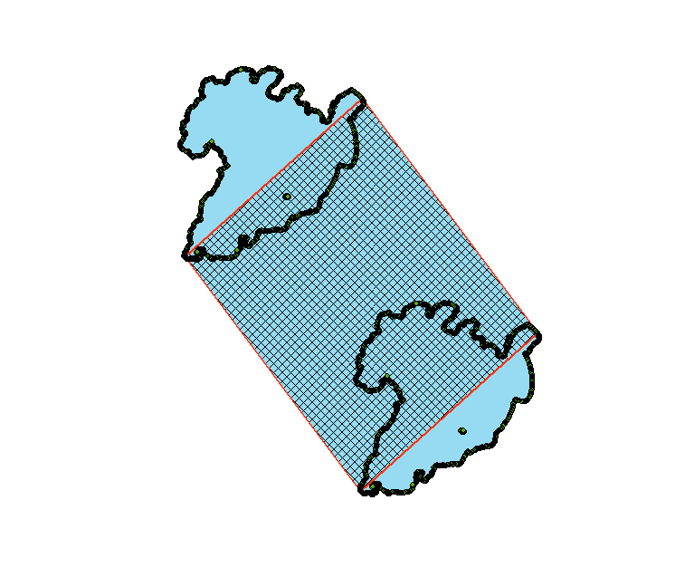
Here is a graphic of what I'm trying to accomplish with ArcGIS...
http://uweb.txstate.edu/~rs1571/polygon.jpg
10-06-2011
08:09 PM
- Mark as New
- Bookmark
- Subscribe
- Mute
- Subscribe to RSS Feed
- Permalink
An interesting task made harder by having too many vertices in a polygon.
100m vertices, are you serious?? The first thing I would do is DICE the glacier up for performance and sanity.
Yes I'm serious. 1M+ polygons, an average of about 80 vertices / polygon. And if I eliminate any of the vertices, then the polygon changes shape and I loose data integrity and my results will be incorrect, unreliable, not of use. Every vertex is a change in azimuth.
I have broken it up based on ~150 unrelated unique polygons, but this is only for conducting processing tests. I wish to not break it up, because in the end I have to reassemble it all anyways. That's a lot more work, and will be done as a last resort measure if none of my systems can handle the processing.
Reason being, once they are all clipped into separate files, while working with one set, increasing a polygon's size along an azimuth at the clipped edge, will cause that polygon to bleed out of the 'bounds', which potentially would have overlapped another polygon that used to be almost adjacent, but is now not present.. clipped out into a separate file. So, now they all have to be merged back and more calculations have to be performed.
Have you considered using rubber sheeting? Now called Spatial Adjustment.
0 Just add a few links to show how much distortion you require and run Adjust.
You would add long links at the tongue and short links at the top.
Put some identity links at the far end to anchor it.
Save your links to enable you to repeat and illustrate.
Ideally rubbersheeting works. The problem is with the size and complexity of my polygons. I would need to somehow, based on the azimuth, determine leading edges and trailing (front and back) edges of every polygon so I knew which vertices were to be displacement links (the trailing) and which would be anchors (leading edges).
This worked great for one polygon...repeating the process a million+ times, no thanks.
Ryan
10-07-2011
01:44 AM
- Mark as New
- Bookmark
- Subscribe
- Mute
- Subscribe to RSS Feed
- Permalink
You haven't tried it!
Adjust doesn't work that way. It works on the whole featureclass, no matter how many polygons or vertices. Coincident vertices will be adjusted by the same amount so the edges will still be coincident.
Adjust defines two error surfaces (TINs) from the vectors and applies a correction to every one of the millions of vertices in the featureclass.
Ah, so the polygons only have 80 vertices each, that sounds better.
If I was considering the flow of a glacier I would be using my open channel flow training to model the ice as if it flowed like water, where the valley is wider, or deeper, the ice would move slower. I could therefore create a velocity field that would be used as a basis to generate the link vectors.
10-07-2011
02:02 AM
- Mark as New
- Bookmark
- Subscribe
- Mute
- Subscribe to RSS Feed
- Permalink
Think of a process to solve the task acting on the whole featureclass at once. ArcGIS is a geo-relational system, like a relational database. When you create an SQL query you don't consider each row of the table, you just specify what you want. The same applies to all the geoprocessing tools. Let ArcGIS sort out the details.
So I did not have in mind clipping out the single feature into 350 featureclasses. Only to split an excessively large polygon into many polygons in the same featureclass. This allows indexing and other efficiencies when processing. That is what DICE does. We would ignore the dicing and just consider the original boundary. I regularly work with millions of features and see no issue with that.
I cannot see any difficulty in designing a process to solve the problem in a few minutes.
Perhaps you want to animate it? How are you defining the 3000 steps? Does it depend on the shape of the polygon boundary? Are the bearing and distance for each step in a table?
Maybe you don't really mean stretched at all? Perhaps "swept area" might be a better term?
Why do you need 3000 steps if the movement is linear?
If it is a linear swept area, all you have to do is convert the vertices to points, copy a set to the final position, join the from-dots to the to-dots at the sides and build a new polygon.
The swept area will have the shape of the front and back preserved with straight sides.
There are simple tools to do all these steps in a series of single steps. Bounding boxes find the max and min vertices, creating lines from points is another and creating polygons from lines another.
If you can't manage a Python script, maybe the modelbuilder would suit, or just manually run the tools.
10-07-2011
03:58 AM
- Mark as New
- Bookmark
- Subscribe
- Mute
- Subscribe to RSS Feed
- Permalink
Swept area
1. Convert large polygon to vertices (Data Management>Features>Vertices To Points)
2. Add an ID field and populate with OBJECTID (AddField, CalculateField)
3. Copy and Paste whole set in editor
4. With pasted still selected move to new final position using Editor>Move...
5. Exit edit
6. Convert outside point pairs to lines (Points To Line) using ID as line field
7. Select the two outer lines, delete the rest, add two lines to create a box
8. Convert 4 closed lines to a polygon (Feature To Polygon)
9. Go back to large polygon, copy and paste and move the same move
10. Union the three polygons
11. Dissolve
Now if you have 3000 steps that trace a path instead of the straight lines, substitute a path instead of the straight line after step 7.