- Home
- :
- All Communities
- :
- Products
- :
- Data Management
- :
- Data Management Questions
- :
- Densify creating vertices at the wrong distance!
- Subscribe to RSS Feed
- Mark Topic as New
- Mark Topic as Read
- Float this Topic for Current User
- Bookmark
- Subscribe
- Mute
- Printer Friendly Page
Densify creating vertices at the wrong distance!
- Mark as New
- Bookmark
- Subscribe
- Mute
- Subscribe to RSS Feed
- Permalink
Hello! I am trying to create transects with points radiating out from a central point in all 4 cardinal directions. The points along the transects are at 1m, 20m, 40m, 60m, 80m, 100m, and then every 100m up to 2200m. I was doing it manually with Direction Distance tool, but it was taking quite a while (20 plots with 4 transects each). I tried to create lines using Direction Distance that went to 100m and 2200m and then to densify those (at 20m and 100m respectively), then to use Feature Vertices to Points to create the points along both transects.
The issue is that when I densify the 2200m transect (line) at 100m increments, it drops the vertices around 96m instead! I recreated the line a few times and did several tests to see if it changed but alas it did not. I didn't have a problem doing this for the 100m transects at the 20m marks. Worked like a charm. I tried densifying the 2200m transects at 20m as well but that also shaved off a bit and dropped the vertices around 17m.
What is going wrong?! Also, if you have a suggestion about how to better do this I am all ears. Till then it's back to the manual creation! Thank you.
- Mark as New
- Bookmark
- Subscribe
- Mute
- Subscribe to RSS Feed
- Permalink
there are a lot of important details in densify that you need to report
Densify—Help | ArcGIS for Desktop
particularly when you say one worked then another didn't, which leads one to suspect that the comparison between the two may not be quite so simple. So, coordinate system? options chose? were the lines straight? anything else ? or better still a visual would be great.
- Mark as New
- Bookmark
- Subscribe
- Mute
- Subscribe to RSS Feed
- Permalink
Thanks Dan. I am using the Projected Coordinate System UTM NAD 1983 Zone
12N for both the 100m and 2200m transects (line features). Yes the lines
are straight. I am using the densify (editing) tool. Using DISTANCE in
meters to densify. Not selecting any other options for offsetting or
anything.
2 screen caps attached. The first (transect2200.jpg) is the zoom out of the
100m and 2200m transects overlapped with the vertices at 20 for the 100m
(which are being placed accurately) and the vertices at 100 (in theory) for
the 2200m transect.
On the close up of the 100m transect (transect100.jpg) you can see that the
red dots (the "100m" vertices of the 2200m transect) do not line up with
the 100m vertex of the 100m transect. On the measure tool you can see the
actual spacing between vertices on the 2200m transect is 95.65.
- Mark as New
- Bookmark
- Subscribe
- Mute
- Subscribe to RSS Feed
- Permalink
The open table was confusing me
Were those lines made as single 2 point polylines? one of them looks a bit weird... and I know that densify does a dance around existing points on a polyline. Now I can't remember off hand whether it just goes as far as it can up to an existing point and adds the fiddly bits after, or whether, it begins again at an existing point. That would be my first check
Then you aren't using that geodesic distance tool/stuff (shouldn't matter over that distance one would think)?
If it is UTM projected, then the points should be as designed, hence my question why one worked and the other didn't.
As a follow up, I would export the polyline to points, then calculate their X,Y coordinates from which you can get the interpoint distances.
- Mark as New
- Bookmark
- Subscribe
- Mute
- Subscribe to RSS Feed
- Permalink
I created the lines by using the Direction Distance tool. Made a point on
the specified bearing 2200m from the centroid, then drew a line by hand
snapping between the centroid and the end point. No other points on the
line.
- Mark as New
- Bookmark
- Subscribe
- Mute
- Subscribe to RSS Feed
- Permalink
I would do the point export thing for sure. I can see maybe points at some distance being off but not over that short a distance. Even if you didn't have a defined coordinate system, the errors are too large for a single-precision versus double-precision issue. If you want to zip and post a shapefile or gdb with just the undensified version of your lines, I can look over it this weekend... or email to my profile email account if you are associated with a university or college
- Mark as New
- Bookmark
- Subscribe
- Mute
- Subscribe to RSS Feed
- Permalink
No... I have the coordinate system use, and I will try to replicate
- Mark as New
- Bookmark
- Subscribe
- Mute
- Subscribe to RSS Feed
- Permalink
Thanks Dan. I am using the Projected Coordinate System UTM NAD 1983 Zone
12N for both the 100m and 2200m transects (line features). Yes the lines
are straight. I am using the densify (editing) tool. Using DISTANCE in
meters to densify. Not selecting any other options for offsetting or
anything.
2 screen caps attached. The first is the zoom out of the 100m and 2200m
transects overlapped with the vertices at 20 for the 100m (which are being
placed accurately) and the vertices at 100 (in theory) for the 2200m
transect.
On the close up of the 100m transect you can see that the red dots (the
100m vertices of the 2200m transect) do not line up with the 100m vertex of
the 100m transect. On the measure tool you can see the actual spacing
between vertices on the 2200m transect is 95.65.
- Mark as New
- Bookmark
- Subscribe
- Mute
- Subscribe to RSS Feed
- Permalink
Okay... we aren't crazy... the problem is the Densify Tool is technically correct, it just doesn't return what we want or perhaps, to be generous, expect.
What the tool does, is guarantees that the points will be ... NO MORE THAN X units apart
Well... that isn't the same as saying... I WANT THEM X units apart.
So rather than doing mental math in the early hours of the morning, I decided to work on demo notes for a class on geometry construction. So, unfortunately, you are going to beta test the procedure ![]()
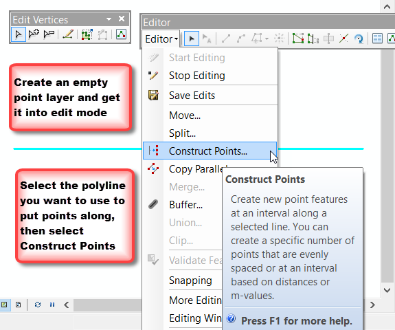
- I added a polyline to a new dataframe ensuring that the layer had a defined coordinate system, and it was a projected coordinate system, since I wanted to work with projected units.
- I created an empty point featureclass (a shapefile in this case). The points were going to be the repository of my new sample locations.
- I then brought up the Edit toolbar and the Edit Vertices toolbar from the Customize, Toolbars menu option.
- The point layer was then put into edit mode and selected my polyline layer, so it was highlighted in the data frame. This polyline layer is going to be 'used' to guide the location of the new points.
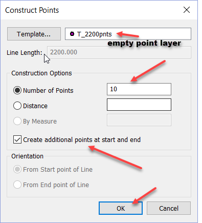
- Through the magic of wizardry, I decided to use the Construct Points tool (see images)
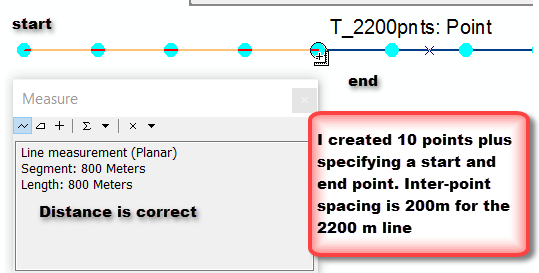
- The points were created and the distances checked.


Now its your turn ![]() . Lesson learned... read carefully the fine print... in this case it was no more than .
. Lesson learned... read carefully the fine print... in this case it was no more than .
There are alternate methods involving code, but I am going to save that for another question in the assignment. So if you have any further questions Bethany, send me an email