- Home
- :
- All Communities
- :
- Products
- :
- Data Management
- :
- Data Management Questions
- :
- Creating Building Outline Polygons
- Subscribe to RSS Feed
- Mark Topic as New
- Mark Topic as Read
- Float this Topic for Current User
- Bookmark
- Subscribe
- Mute
- Printer Friendly Page
Creating Building Outline Polygons
- Mark as New
- Bookmark
- Subscribe
- Mute
- Subscribe to RSS Feed
- Permalink
I am trying to develop an efficient method of creating polygons for Building Outlines and am looking for feedback on the processes I have tried.
I am not able to get my aerial images to work with Spatial Analyst given the way they are configured and being served, so I have never gotten off the ground with any approach based on the Spatial Analyst extension or tool set. Plus I want clean vector outlines, which I am not sure Spatial Analyst will produce.
I want tract houses of the same model type to have an attribute identifying their model type during the process. I have tried creating template polygons of the base models in a tract and assigning sequential numbers to each separate model type. I also used the Mirror tool to create the reversed models and identified them either with the next sequential number after their parent model or using the same right-justified number string as the parent model with an R at the end.
I found that even though I could copy and move these base model polygons to other houses in the tract, it was tedious to locate the nearest matching copy of the model I wanted, make a new copy of that model polygon, drag it to overlap the new house, and perform a rotation until every thing aligned the way I wanted. Plus these polygons had no real attributes beyond their model type.
My latest effort is now using these steps:
1. Grab a screen shot of a portion of the tract that has all of the models and paste it into a graphics program and trace models oriented with their frontages on the north or adjust the orientation of each model to a single orientation in the graphics program.
2. Trace the outline of each model as black vector lines with a black fill (the absolutely solid single color is important for a later step) and export each model as a separate emf file using the same naming convention I was using to attribute the model polygons. I use the horizontal mirror tool in the graphics program to make each model's mirror layout emf file as well and give it an appropriate emf name.
3. I used my address points which were extracted from the parcel centroids and added three fields to the points, which were Model_Number, Model_Rotation, and Distance, I also make sure each address has a single field with a unique ID value other than the ObjectID. In my case I calculated a concatenation of the address point X and Y coordinates which works for the vast majority of address points.
4. I assign the emf file names to the Model_Number field for the known model locations I had traced in the graphics program so that they will match the symbol categories assigned in Step 6..
5. I set a reference scale on my data frame that will keep all symbols on the address points displaying at a set size. I have found 1 inch:4000 inches to be a good reference scale for this purpose.
6. I created a Category symbology from the Model_Number field of my address points and assign the.corresponding emf file as a marker symbol. I set the Advanced Rotation option for the symbology to use the Model_Rotation field and Arithmetic degrees. I set the layer transparency to 50% so I could see the aerial behind each marker.
7. I initially assign 90 degrees to the Model_Rotation field for the traced models and make adjustments to the font sizes of each model symbol until each model appears to be the same size as the one shown on the aerial image and move the address point until I am satisfied the model is centered on the image.
8. I select all address points in the tract and assign them one of the model numbers just so I can see their frontage orientations in a later step.
9. I add the Linear Referencing road routes I have created for my centerline network and select the set of roads the address points fall along.
10.. I use the Locate Features Along Routes with the create a Distance field option and the keep all matches option and use a search radius of about 100 feet in a standard tract to convert them to a linear referenced event table.
11. I create a Route Event Layer from the event table and use the distance field as an offset distance and set the advanced options to generate a normal angle field. I make sure the advanced setting for side offsets makes the points appear on the correct side of the road.
12. I select only those address point records that matched the road name (which my LR Routes include in their ID) with an SQL statement like RID Like CONCAT(BASE_STREET_NAME, '%').
13. I export the Route Event Layer selection to create a point feature class that permanently stores the normal angle field value for each address point relative to the road.
14. I create a join on a unique ID field for the address points and calculate the LOC_ANGLE field values into the MODEL_ROTATION field and the Distance field values into the DISTANCE field of the address points. Then I break the join.
15. I select all address points with a negative (or positive) distance value that appear to be oriented 180 degrees the wrong way and subtract 180 from the MODEL_ROTATION field to verify that they rotate to more or less the correct orientation on address points that are perpendicular to the street. The majority of houses should now appear oriented correctly, unless they are located around the ends of cul-de-sacs, in street knuckles, outside the search radius of step 10, or just not perpendicular to the road. Here is a screen shot of what my data looks like at this stage:
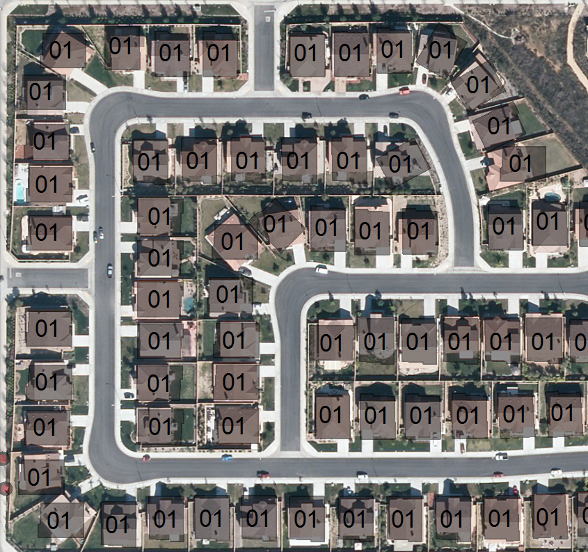
16. I label the model markers in the center with their model number and then begin the process of identifying each model I see and correcting the model numbers to the correct one.
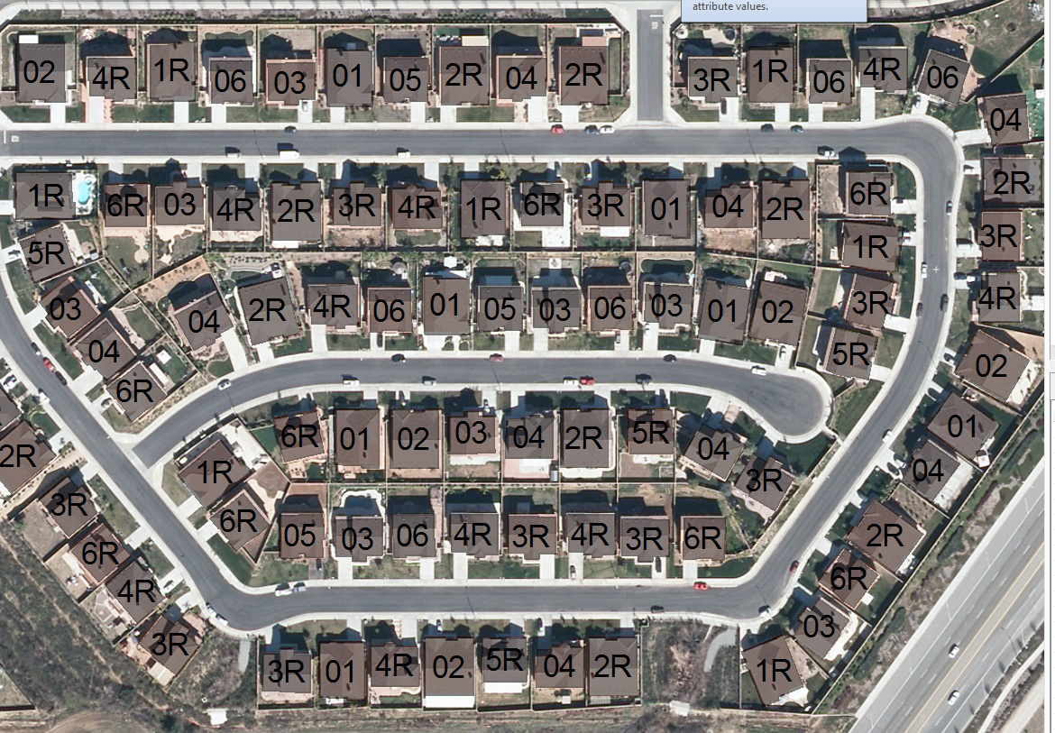
17. I make minor adjustments to the MODEL_ROTATION field as necessary, especially at the ends of cul-de-sacs, for elbow angles in the road network and for houses that were outside the search tolerance, and move the address point until the house model is centered. Here is what a completed portion of the tract looks like:
18. When the whole tract is done I turn off every layer except my address points with the model markers (use a definition query if necessary). I turn off any address point labels I had on and set the transparency of the address point markers to 0 so the markers are completely black against a white background.
19. Zoom to the scale and location that encompasses your project area.
20. Click File > Export Map > Save as type: TIFF
21. In the options drop down > Format tab check 'Write GeoTIFF Tags'. You can change the color mode to monochrome and in the general tab you should increase the resolution to 300 dpi or greater and set the width/height to make the house lines look smooth (you may have to experiment to get the best values here).
22. Export the map and then add the TIFF file back into the map. It should render in the correct location due to the GeoTiff tags. Turn off the address markers so that only the GeoTiff layer appears on screen.
23. Open the Raster to Polygon tool (Toolboxes\System Toolboxes\Conversion Tools.tbx\From Raster). Click the Simplify Polygons option and fill out the other parameters. It shouldn't matter what you put for Field because in this case you don't care what the pixel values are for the raster.
24. Run the tool and it will convert the raster into polygons. You will have to delete the background polygon surrounding your actual building outlines in order to only get the housing footprints.
25. Use the Spatial Join tool with the building footprint polygons as the Target and the Address Points as the Join features. The One-To-One settings and closest feature settings should be fine. The Spatial Join output is the final output of building footprints polygons.
Some benefits of this method is that each address point is now optimally centered within the house outline, both the address point and the house outline polygons have an angle field showing the orientation of the frontage of the house, and the house outline polygons have address information. These items will very likely be useful for other purposes.
Steps 1 through 15 and Steps 18 through 25 don't take that long now that I have worked out the steps. The most tedious part is still determining the model type in Step 16 and somewhat the fine detail positioning in Step 17, but it is much easier than trying to find a previously created polygon that matches and try to move a copy of of that polygon on top of another house.
- Mark as New
- Bookmark
- Subscribe
- Mute
- Subscribe to RSS Feed
- Permalink
By the way, for Step 16 it helped when I paid attention to the driveway location to determine if I was supposed to use the parent model or the mirror image/reversed model.
Having a model number attribute will make it easier to assign other attributes of the model houses, like number of floors, bathrooms, bedrooms, etc when I correlate them to building permit data.
These shapes should also help me refine my building permit shapes which currently are shaped like the parcel that existed when the building permit was submitted. Sometimes the permit shape is the entire subdivision boundary if the Assessors had not subdivided the property prior to the building permit being submitted. Those shapes are not very useful..
- Mark as New
- Bookmark
- Subscribe
- Mute
- Subscribe to RSS Feed
- Permalink
It appears that this method is more powerful than I thought and at least in my case. I believe I can solve a significant portion of the Step 16 time consuming process of manually identifying the correct model number for each address from aerials within a large portion of my tracts.
1. It turns out that the address points had the parcel number they were associated with so they could be linked to parcel data.
2. The parcel data had legal description information that I appended to the addresses.
3. The legal description (Tract and lot) could be concatenated in a standard format that matched a field in my building permit data so that I could create a join on the concatenated legal description field of the addresses to my Building Permits.
4. I extracted the residential building permits that had reached a status of Final and that had a model number specified in their description field.
5. I parsed out the Model Number into its own field from the description. Each tract typically used model numbers starting at 1. Often the reverse/mirrored version was followed by an R, but not always, so I did have to manually add an R version when the plan was reversed in the case of several tracts. Sometimes model numbers would have letters like A, B, or C after the number to indicate variant versions of the base model number.
5. I calculated the MODEL_NUMBER for the addresses to be the parsed Model Number from the permit description followed by the Tract Number. Using these values means that the model numbering is not randomly assigned, but connected to real permit model numbers. This will help associate the shapes to any permit plans that may exist. Although I do not have access to those plans, someone else in my jurisdiction does and could probably help me create a hyperlink to scanned files of the plans for their use.
6. These Model_Numbers will be used for the emf file names. If I find that multiple tracts used the same model set I don't have to draw each model and can simply group that set of tracts for each model number in the layer symbol categories once I had created the emf file for one of the tracts.
This process worked for 35032 address points. If every tract phase model set was unique then there would be 7,236 unique model numbers. However, a majority of the tract phases would use the same model set as the final phase despite the different map numbers, so probably less than a third of that amount are actual unique models footprints.
So for a significant portion of my data as soon as I can create and apply an emf drawing of the model set for a given tract to the address point layer symbology, the model outlines will immediately appear somewhere within the all of the correct lot numbers for that tract. Then the only time consuming part will be fine tuning of the rotation and position of the building outlines and validating an odd appearing address/permit associations created by user error when the permit data was typed.
- Mark as New
- Bookmark
- Subscribe
- Mute
- Subscribe to RSS Feed
- Permalink
For anyone wanting to create emf files, I have found that PowerPoint is the easiest editor to work with that outputs a clean emf file. Illustrator is hard to set up to avoid unwanted background elements in the emf file.
Pasting an image into PowerPoint is easy to do by just pressing the paste button after doing a screen capture (Print Scrn button). I use the freeform drawing shape from the Drawing group on the Home tab to create a closed polygon. I also use the Fill Shape and Shape Outline drawing tools on the Home tab to adjust the color of the shape to solid black. When the shape is selected I can use the Drawing Tools Format tab for the Rotate tools (rotation of mirrored flips) to adjust the orientation of the shape to make the house front face north and create its mirrored layout.
I have changed my Model Number values to put the tract first followed by the model. This makes symbols sort together in the symbology tab, which makes them easier to work with.
- Mark as New
- Bookmark
- Subscribe
- Mute
- Subscribe to RSS Feed
- Permalink
Since then, have you by chance ever had occasion to extract building footprints from the Esri basemaps?
I'd like have establish an living inventory of our community's building stock, using the existing building footprints as a starting point.