Turn on suggestions
Auto-suggest helps you quickly narrow down your search results by suggesting possible matches as you type.
Cancel
- Home
- :
- All Communities
- :
- Developers
- :
- ArcObjects SDK (Retired)
- :
- ArcObjects SDK Questions
- :
- Re: BoreHole 3d NoVertical Line - How can I calcul...
Options
- Subscribe to RSS Feed
- Mark Topic as New
- Mark Topic as Read
- Float this Topic for Current User
- Bookmark
- Subscribe
- Mute
- Printer Friendly Page
BoreHole 3d NoVertical Line - How can I calculate it ?
Subscribe
3547
5
08-03-2011 05:47 PM
08-03-2011
05:47 PM
- Mark as New
- Bookmark
- Subscribe
- Mute
- Subscribe to RSS Feed
- Permalink
Hi all.
I am trying to create a borehole inclined line, but I just could create a vertical line using the fields X, Y, From, To fields.
I would like to create a no vertical (the line inclined with angle). I have other fields (Azimuth, Dip, Z, Depth), but I don't know the calc for it.
Below. The piece of code. It is working well and it can create a vertical line. But I am not sure how can I create a no vertical line
Set pPointCollection = New Polyline
Dim pzawarePC As IZAware
Set pzawarePC = pPointCollection
pzawarePC.ZAware = True
' get first coordinate and store
pPoint.x = pRow.Value([XField])
pPoint.y = pRow.Value([YField])
Dim pZAware As IZAware
Set pZAware = pPoint
pZAware.ZAware = True
pPoint.Z = pRow.Value([TopField])
pPointCollection.AddPoint pPoint
' get second coordinate and store
pPoint.x = pRow.Value([XField]) + 0.00001
pPoint.y = pRow.Value([YField])
Set pZAware = pPoint
pZAware.ZAware = True
pPoint.Z = pRow.Value([BottonField])
pPointCollection.AddPoint pPoint
' store the pointcolletion in the featurebuffer
Set pFeature.Shape = pPointCollection
Fields that I am not using from my shape (Z, Depth, Dip, Azimut)
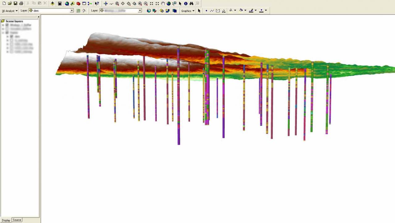
Below the printscreen about two lines. The vertical line was created using the calc above. The second line was created using the ArcHydro tool.

I am trying to create a borehole inclined line, but I just could create a vertical line using the fields X, Y, From, To fields.
I would like to create a no vertical (the line inclined with angle). I have other fields (Azimuth, Dip, Z, Depth), but I don't know the calc for it.
Below. The piece of code. It is working well and it can create a vertical line. But I am not sure how can I create a no vertical line
Set pPointCollection = New Polyline
Dim pzawarePC As IZAware
Set pzawarePC = pPointCollection
pzawarePC.ZAware = True
' get first coordinate and store
pPoint.x = pRow.Value([XField])
pPoint.y = pRow.Value([YField])
Dim pZAware As IZAware
Set pZAware = pPoint
pZAware.ZAware = True
pPoint.Z = pRow.Value([TopField])
pPointCollection.AddPoint pPoint
' get second coordinate and store
pPoint.x = pRow.Value([XField]) + 0.00001
pPoint.y = pRow.Value([YField])
Set pZAware = pPoint
pZAware.ZAware = True
pPoint.Z = pRow.Value([BottonField])
pPointCollection.AddPoint pPoint
' store the pointcolletion in the featurebuffer
Set pFeature.Shape = pPointCollection
Fields that I am not using from my shape (Z, Depth, Dip, Azimut)
Below the printscreen about two lines. The vertical line was created using the calc above. The second line was created using the ArcHydro tool.
5 Replies
08-04-2011
03:53 PM
- Mark as New
- Bookmark
- Subscribe
- Mute
- Subscribe to RSS Feed
- Permalink
Have you tried using an offset larger than .00001 in the line?
pPoint.x = pRow.Value([XField]) + 0.00001
I suspect that that value is within the cluster tolerance and so your second point is actually collapsing on top of your first point.
I think your code should work and it looks a lot like what I have done in the past, that is, offset the bottom point a negligible amount so that you can measure it and locate route events on it.
Try creating your code-based line in the same feature class container that the ArcHydro line is in.
08-05-2011
06:52 AM
- Mark as New
- Bookmark
- Subscribe
- Mute
- Subscribe to RSS Feed
- Permalink
thanks Evans. I have tried resize that number. But it did not work well. I believe that for each segment and borehole there is the inclination. I think that it is calculated using the delph, dip and azimuth.
08-10-2011
10:41 AM
- Mark as New
- Bookmark
- Subscribe
- Mute
- Subscribe to RSS Feed
- Permalink
Crisjovano,
Sorry! I misunderstood your first post.
What I would do is first create a single directional borehole line, turn it into a route, and then locate the borehole intervals along its length.
This is what I did recently for this very exercise using available tools.
1) Your X, Y, Z, azimuth, dip, and depth values are the same for every borehole, so normalize your intervals table into a table where each row is a different borehole. Then create two new fields, 'horizontal' and 'vertical' for instance. The horizontal value is going to be the length of the line in 2d as if you were looking down on the line in plan view. The vertical value is going to be the distance down from the plan view horizon to the bottom of the borehole. Horizontal = cos(dip) * depth and Vertical = sin(dip) * depth.
2) Create 2d lines using the 'Bearing Distance to Line' tool in Data Management. Use the X, Y, azimuth, and HORIZONTAL (not depth) fields.
3) Put these lines in a Z-aware feature class and enter the borehole collar elevation ('Z') and borehole bottom elevation ('Z' - 'vertical') for each line.
4) Turn these lines into routes using the Create Routes tool. Take care with the coordinate priority so that your boreholes get measured from top to bottom and use the 'ONE FIELD' parameter for the measure source and set From-Measure Field to the depth value.
5) Use the Locate Features Along Routes tool to place the borehole intervals along the measured borehole lines.
If you need to automate this, I would recommend python over ArcObjects
12-18-2011
10:25 AM
- Mark as New
- Bookmark
- Subscribe
- Mute
- Subscribe to RSS Feed
- Permalink
Hi Byambaa88. it is a vertical borehole, right ?