- Home
- :
- All Communities
- :
- Developers
- :
- ArcObjects SDK
- :
- ArcObjects SDK Questions
- :
- Re: ArcObjects Custom Geoprocessing Tool SpatialRe...
- Subscribe to RSS Feed
- Mark Topic as New
- Mark Topic as Read
- Float this Topic for Current User
- Bookmark
- Subscribe
- Mute
- Printer Friendly Page
ArcObjects Custom Geoprocessing Tool SpatialReference Question
- Mark as New
- Bookmark
- Subscribe
- Mute
- Subscribe to RSS Feed
- Permalink
I am looking for some conceptual guidance to make sure I am on the right track in how I should deal with spatial references in a geoprocessing tool. Any .Net code is appreciated, especially if it is in VB.Net, but at least initially I am more concerned that I am making the best overall design decisions for how my tool should behave. I have to provide a fair amount of background before getting to my questions, so I have highlighted my questions so that they are easier to pick out.
I want my custom geoprocessing tool to behave as much as possible like any other Esri geoprocessing tool, but I am struggling with some complexities related to the spatial reference requirements of the tool. The tool is ultimately supposed to buffer a polyline input using a custom buffering routine that prevents overlap of the buffers where the lines intersect in the polygon output. I developed the code to do the buffering in a VS Project that was not designed as a geoprocessing tool, and currently it only works with hard coded inputs and outputs that use the same Projected Coordinate System (PCS) spatial reference that my data commonly uses. I want to change this code to use a custom tool interface that will let the user configure the input and output work spaces and feature class names and I want it to work for a wide variety of spatial references.
I have separately developed a basic custom geoprocessing tool interface that can take any polyline input in any spatial reference and output an empty polygon feature class to any work space and feature class name. The output polygon field schema is derived from the polyline field schema and validated for the output work space. The output spatial reference will be the same as the input spatial reference except when the user either chooses an output Feature Dataset with a different spatial reference from the input or chooses a work space that is not a Feature Dataset and sets the Output Coordinate System of the geoprocessing environment settings to a different spatial reference from the input. Do these behaviors sound like they follow the common geoprocessing tool behaviors that users expect in Esri's geoprocessing tools, or have I overlooked something? I can provide the code in a later post if you are interested in how I got the tool to do these behaviors.
Currently my basic custom geoprocessing tool can have both the input and output in a Geographic Coordinate System (GCS), but unlike Esri's tools I do not want to support that option in my completed tool, since I want my buffers to be based on Linear Units. I do not want to have to figure out how to implement Linear Buffers and determine bearings in a coordinate system that uses angular units. Should I alert the user that they cannot make the input and output both use a GCS by adding an error message on the output feature class in the UpdateMessages portion of the tool when I detect that both the input and output will use a GCS?
I would like my tool to work if either the input or output uses a Projected Coordinate System (PCS). If the input is in a PCS I plan on using a search cursor to directly read the polyline geometry into a dictionary and use the input coordinate system for the buffering steps. I would only project the polygon geometry created in memory right before storing it in the output shape field if the output is in a different coordinate system.
If the input is in a GCS, then the output would have to be in a PCS. I would want to project the polyline geometry of the input after reading it using a cursor and prior to storing it in the dictionary. After that the buffering and output polygon would all use the output spatial reference.
Assuming I figure out how to control the logic of choosing the spatial reference the code will use for the buffering, I was thinking of using the IGeometry2.ProjectEx method to actually do the projection of either the output polygon or the input polyline when that step is necessary. I would like to use that method to handle densification of the geometry. Does that sound like the approach I should take?
If the user specifies a different spatial reference for the input and output I have developed code that can read the environment settings to configure any geographic transformation chosen by the user. However, since the geographic transformation list presented in the environment settings contains so many irrelevant transformations, should I instead add an optional parameter to the tool interface where the user would choose a transformation from a narrower list of transformations that fit the input and output spatial references? I have seen some code that I should be able to adapt that would do that. If I set up that list, then the user should only be required to choose a transformation if the input/output spatial references have different underlying GCS's. Is there a help reference for how to make a parameter only appear when it is required? Or should I just make my transformation parameter an optional parameter that is always present and then only add an error message when the input/output require it?
Thanks in advance for any input you can provide.
- Mark as New
- Bookmark
- Subscribe
- Mute
- Subscribe to RSS Feed
- Permalink
I moved this to a new place to hopefully generate at least one comment. I would at least hope that Melita Kennedy or Dan Patterson could give this post a look and offer some suggestions.
- Mark as New
- Bookmark
- Subscribe
- Mute
- Subscribe to RSS Feed
- Permalink
Richard, just curious, have you thought about using Python?
I'm curious to see how this all works and see if it may be something that I would want to adopt for one of my projects. Currently when I buffer my flight line transects I allow them to overlap and have gaps, which may be ok in my situation, but since I'm revisiting one of my projects and rewriting everything in python (some parts are still aml and avenue), I may see if removing the gaps/overlays will be something that would improve our analysis of the field data. So, I'll be following the thread with interest.
- Mark as New
- Bookmark
- Subscribe
- Mute
- Subscribe to RSS Feed
- Permalink
Rebecca:
For my tool I am using several fairly low level geometry operations supported by ArcObjects that do not have any obvious equivalent in Python. Additionally, my original data uses true curves and I want a tool that supports the use of true curves, which Python does not do. Those are my primary reasons for doing this in ArcObjects.
As far as the code I created for the buffers it was developed in response to this thread and started really taking shape beginning at about the 9th post.
Your flight lines would need to be in a projected coordinate systems for my tool to work, since as I mentioned it is too complicated for me to work with angular units and bearings. If your flights cover large areas of the globe, projected coordinate systems may not be suitable for your analysis, since they may produce too much distortion in one or more of the geometry measurements you are wanting to evaluate. Additionally, the buffer width my application expects should be relatively narrow, since the geometry operations start creating too many self overlaps and other strange artifacts or just plain fail if the buffer width is too far from the original line.
- Mark as New
- Bookmark
- Subscribe
- Mute
- Subscribe to RSS Feed
- Permalink
Thanks Richard. Yes, my data is projected and my buffers are relatively small (max about 650 m). I already have python scripts tools where I go thru each transect and buffer a segment at a time....and it is based on whether they were looking out the left or right side of the plane. I recently (last year) had to retrofit our flight lines to break each individual transect into 1 KM segments (vs the multi-past 30 KM) so the biometrician could test out different theories. This of course created many more segments that had to be buffered. I had a few that for no reason (tech support and I could never figure it out) would actually created a full circle as part of the buffer....not a geometry error or anything, just random. But the program would run for multiple days so who knows what hiccup it ran into.
Anyway, with all these additional segments, I had quite a bit of manual cleanup to do. It was a rush project...that is, since programs ran for days on end, I had to get the programs to do what they could in a short time. Anyway, this question and the other threads going around (thanks for the link) intrigued me.....so may see if I can incorporate some of these concepts when I next work on it. This is a once ever few years field project (with lots of data crunching afterwards) which is why some of my programs are still old. But we have another coming up next year so I'll be back on it soon to update them all. It's a fun project (and has seen many changes since our first in '92).
So, not quite the same as you need, but worth following to see if you get anything more suggestions.
- Mark as New
- Bookmark
- Subscribe
- Mute
- Subscribe to RSS Feed
- Permalink
Firstly, I am splitting the questions out into individual responses so that any subsequent comments can target a single issue.
The output spatial reference will be the same as the input spatial reference except when the user either chooses an output Feature Dataset with a different spatial reference from the input or chooses a work space that is not a Feature Dataset and sets the Output Coordinate System of the geoprocessing environment settings to a different spatial reference from the input. Do these behaviors sound like they follow the common geoprocessing tool behaviors that users expect in Esri's geoprocessing tools, or have I overlooked something?
As far as spatial references go this seems to be consistent with the way that the Esri geoprocessing tools work. When creating a feature class inside a Feature Dataset you must use the spatial reference of the feature dataset. In ArcObjects you will get an error if you attempt to create a feature class inside a Feature Dataset and the coordinate systems don't match.
- Mark as New
- Bookmark
- Subscribe
- Mute
- Subscribe to RSS Feed
- Permalink
Owen:
Thanks for your comments. Overall it sounds like I am on the right track. I have discovered that several geoprocessing tools ignore the spatial reference setting, such as GPX to Points (did not expect that) and Project (makes sense since you have to set the output spatial reference explicitly with the tool). In this case, since I want the user to be able to get to a Projected Coordinate System from a GCS input, supporting a new spatial reference through these two options saves them the step or Projecting their data separately.
- Mark as New
- Bookmark
- Subscribe
- Mute
- Subscribe to RSS Feed
- Permalink
I hadn't tested using the Geoprocessing > Environment > Output Coordinates settings previously, However I can confirm that the GPX to Feature tool does seem to ignore the setting:
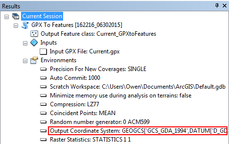
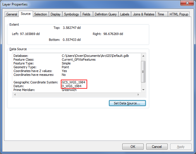
In this test you can see that the output should have been GCS_GDA_1994 but the feature class was created in GCS_WGS_1984. Maybe someone from ESRI can comment on this? - Melita Kennedy
- Mark as New
- Bookmark
- Subscribe
- Mute
- Subscribe to RSS Feed
- Permalink
The answer's in the tool help twice! 
I went to check this section first, because it should tell you which, if any, of the gp environment settings apply.
Environments
This tool does not use any geoprocessing environments
But as I was scrolling down, my eye spotted this note:
Output will be generated in the WGS84 coordinate system. The output features can be reprojected to another coordinate system, if desired, using the Project tool.
Melita
- Mark as New
- Bookmark
- Subscribe
- Mute
- Subscribe to RSS Feed
- Permalink
Doh!
In most cases I at least scan the help content - this was obviously not one of those times. 