Turn on suggestions
Auto-suggest helps you quickly narrow down your search results by suggesting possible matches as you type.
Cancel
- Home
- :
- All Communities
- :
- Products
- :
- ArcGIS Spatial Analyst
- :
- ArcGIS Spatial Analyst Questions
- :
- Topo to Raster: Forcing an input constraint
Options
- Subscribe to RSS Feed
- Mark Topic as New
- Mark Topic as Read
- Float this Topic for Current User
- Bookmark
- Subscribe
- Mute
- Printer Friendly Page
06-04-2013
01:37 AM
- Mark as New
- Bookmark
- Subscribe
- Mute
- Subscribe to RSS Feed
- Permalink
Hi all,
I've hit a bit of a wall in my work and was wondering if there was anyone out there that could help me out.
I'm trying to use the Topo to Raster function to create an interpolated elevation surface with both contour and point inputs. I can create a standard interpolated surface just fine using the default settings but what I actually wanted was to force the interpolated surface to equal these contour and/or point input constraints at their respective locations (since the data at these points are essentially known to be "exact"). Does anyone have any ideas on how to do this or if this is possible in ArcGIS/ArcScene?
Any help would be greatly appreciated!
Regards
Robin
Solved! Go to Solution.
1 Solution
Accepted Solutions
06-06-2013
07:57 AM
- Mark as New
- Bookmark
- Subscribe
- Mute
- Subscribe to RSS Feed
- Permalink
In producing these supplemental contours, did you simply use linear interpolation between primary 2.5 inch contours?
I created a "web" with polylines going back and forth between the existing isohyets and then using a keyboard stroke (Ctrl-F7) to snap to the centerline of the web polyline segments drew in the supplemental isohyets. So, basically, yes, I "interpolated" between the existing isohyets. The density of the web polylilnes dictated the smoothness of the supplemental isohyets.
Also, the final isohyets in Figure 19, are they extracted directly from the interpolated raster? Because they look really good.Yes. The final raster was 100'X100', so the isohyets turned out nicely.
7 Replies
06-04-2013
04:25 AM
- Mark as New
- Bookmark
- Subscribe
- Mute
- Subscribe to RSS Feed
- Permalink
The thine plate spline interpolation technique is used in the Topo to Raster tool per the help, which should force the interpolation to match at the specific elevation points, but may be adjusted slightly during the iterations. The iterations inherent in the tool are used to create a 'hydro-logically correct model.' You can control the number of iterations it performs in the tool.
If you are looking for an additional look, I would consider Terrain/TIN generation to utilize the points and lines. Generally I would make the points mass points and the contours soft breaklines, but if you are adamant that they must be maintained, then make the hard breaklines. In practice this sometimes creates stair steps in the output but the values should match at the contour for your client.
If you are looking for an additional look, I would consider Terrain/TIN generation to utilize the points and lines. Generally I would make the points mass points and the contours soft breaklines, but if you are adamant that they must be maintained, then make the hard breaklines. In practice this sometimes creates stair steps in the output but the values should match at the contour for your client.
06-04-2013
09:11 AM
- Mark as New
- Bookmark
- Subscribe
- Mute
- Subscribe to RSS Feed
- Permalink
I did work along this line with mean seasonal isohyets which are basically contours of equal rainfall. The work is documented here:
http://www.cccounty.us/DocumentCenter/Home/View/3914
http://www.cccounty.us/DocumentCenter/Home/View/3914
06-04-2013
10:03 PM
- Mark as New
- Bookmark
- Subscribe
- Mute
- Subscribe to RSS Feed
- Permalink
Thanks Jeff and Mark for your answers.
Jeff - As far as I understand, you say that the algorithm for Topo to Raster should have the surface be matching the input at their respective points but this may be changed as it further iterates until it achieves a "hydro-logically correct model"? In this case, could I set the number of iterations to 1 in order to make the surface match the inputs as much as possible (where the tradeoff would be a less hydro-logically correct model)? I will have to play around with mass points and breaklines, they sound interesting.
Mark - Very interesting work, I enjoyed reading that. So essentially you created additional contours where you thought the initial interpolation was not behaving as expected to constrain the subsequent interpolations better? In producing these supplemental contours, did you simply use linear interpolation between primary 2.5 inch contours? Also, the final isohyets in Figure 19, are they extracted directly from the interpolated raster? Because they look really good.
An idea I had was to just pass the more important points as inputs multiple times into the interpolation to weight it more, I'll have to see if this is a legitimate idea later.
To put things in perspective, I've attached an image of my work too. The important things to note here are the surface was interpolated using the contours (brown lines) and green points. The purple points are the extracted surface elevations from the interpolated surface at the same latitude and longitudes as the green points. As can be seen, there are some large differences in some areas, up to 80 metres. What I'd like to achieve is the interpolated surface to pass through the green points (or pass by them extremely closely)
06-05-2013
04:38 AM
- Mark as New
- Bookmark
- Subscribe
- Mute
- Subscribe to RSS Feed
- Permalink
Have you tried to create the TIN/Terrain? That might be better for containing the points from your description. Or fall back on a Spline interpolation to stretch the interpolation around the points. Take a look at page 35 on the this pdf document talking about the different interpolation techniques.
06-06-2013
07:57 AM
- Mark as New
- Bookmark
- Subscribe
- Mute
- Subscribe to RSS Feed
- Permalink
In producing these supplemental contours, did you simply use linear interpolation between primary 2.5 inch contours?
I created a "web" with polylines going back and forth between the existing isohyets and then using a keyboard stroke (Ctrl-F7) to snap to the centerline of the web polyline segments drew in the supplemental isohyets. So, basically, yes, I "interpolated" between the existing isohyets. The density of the web polylilnes dictated the smoothness of the supplemental isohyets.
Also, the final isohyets in Figure 19, are they extracted directly from the interpolated raster? Because they look really good.Yes. The final raster was 100'X100', so the isohyets turned out nicely.
06-09-2013
08:09 PM
- Mark as New
- Bookmark
- Subscribe
- Mute
- Subscribe to RSS Feed
- Permalink
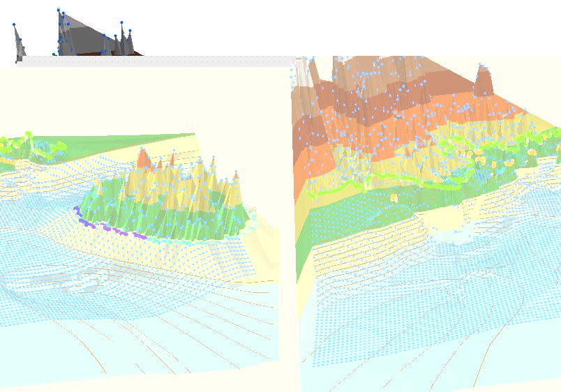
Okay! I created a TIN and I think it worked out nicely (I've attached an image in case either of you were interested in seeing the result, I checked the values at the point constraints and they are indeed exact). As it consists of triangles, it's obviously not smooth and such as a raster would be but since I discretize it into points anyway it shouldn't be much of an issue. I will talk to my supervisor about the result sometime in the near future and see what he thinks.
The only real problem I have with this now is the extremely steep patch just left of the centre which has no contours and also few discretized points (blue points) to characterize it. A finer mesh and some interpolated contours may fix that though.
Also Mark, your way of creating this web may be very useful for some work that I have been stuck on for the past few days (step by step extrapolation of contours);)
Thanks very much to both of you for your help, I may be back if any other issues arise 😛
06-10-2013
04:50 AM
- Mark as New
- Bookmark
- Subscribe
- Mute
- Subscribe to RSS Feed
- Permalink
I am glad that the TIN was able to display it in a manner you liked. Also as you pointed out, in the absence of data, it will get weird in places. So the tools originally mentioned are better adapted to resolve the lack of data and smooth it out, ie Topo to Raster. For your requirement of having the contours followed precisely, there are some trade offs. Best of luck with your analysis.