- Home
- :
- All Communities
- :
- Products
- :
- ArcGIS Spatial Analyst
- :
- ArcGIS Spatial Analyst Questions
- :
- Re: Problems about Euclidean Tool(Euclidean alloca...
- Subscribe to RSS Feed
- Mark Topic as New
- Mark Topic as Read
- Float this Topic for Current User
- Bookmark
- Subscribe
- Mute
- Printer Friendly Page
Problems about Euclidean Tool(Euclidean allocation)
- Mark as New
- Bookmark
- Subscribe
- Mute
- Subscribe to RSS Feed
- Permalink
Hi,
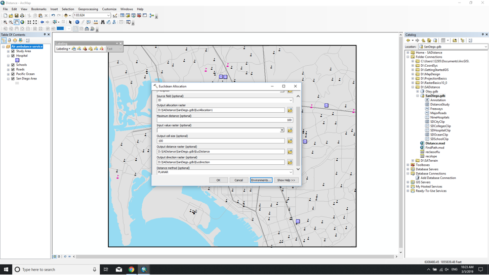
I've run in to some problems when I've tried to use the euclidean-distance tool. As you can see on the picture the results are not displayed on the existing layers
I also read the posts provided by specialists in GeoNet, and try to change the content in environment button, then I get a result of three layers, but they cannot be seen on the existing layers...
Have anyone got an idea what I'm doing wrong?
Thanks!
Solved! Go to Solution.
Accepted Solutions
- Mark as New
- Bookmark
- Subscribe
- Mute
- Subscribe to RSS Feed
- Permalink
I had a similar issue as what you have. I believe we are doing the same practice. You actually inspired me as when I follow the instructions, I always had the error message related to the SDCityClip polygon data, which has been set in the Environment as the mask layer. But the data layer loaded in the map file has a different layer name, San Diego Area. So I changed the mask layer to San Diego Area.
After I explored a few options, I found out you have to change another two settings to get the correct results.
1. Select Hospital_C as the source field. I was confused when I checked the attribute table to see ID values are not unique for each hospital. I think the point is you need unique values to distinguish all source points, hospitals in this case.
2. Do not use 100 in Maximum distance. Just leave it empty. I think this limits the results to only 100 feet around all hospitals. That's why you thought you cannot see the data layer. The data layer actually only have the data of four neighbor pixels around each hospital, which can hardly to been seen in the map.
Finally, I got the results same as what shown in the instructions... Hope you also figured it out.
I do think the course did a very poor job providing correct instructions. Probably need to report to ESRI.
- Mark as New
- Bookmark
- Subscribe
- Mute
- Subscribe to RSS Feed
- Permalink
projections different?
right-click on one of the layers you can't see and select Zoom to Layer.. does it appear
- Mark as New
- Bookmark
- Subscribe
- Mute
- Subscribe to RSS Feed
- Permalink
thanks Dan! I tried but there is no layers appeared.. then I try the change the sequence of those layers, still no appearances...
- Mark as New
- Bookmark
- Subscribe
- Mute
- Subscribe to RSS Feed
- Permalink
Alright, when making the output files specify a folder as the destination and a *.tif file as the output raster.
It sounds like the files aren't being created because the path to the destination is too convoluted, contains a space, begins with a number, the name is more than 13 characters or some other thing.
so c:/temp/euc01.tif for example make sure you are using a known output coordinate system preferably a projected one and not Web Mercator, something like UTM
- Mark as New
- Bookmark
- Subscribe
- Mute
- Subscribe to RSS Feed
- Permalink
Well, I just tried it again, something makes me feel so confused:
this is my instruction:
On the Standard toolbar, click the Search button ![]() .
.
Search for Euclidean.
Open the Euclidean Allocation tool.
In the Euclidean Allocation dialog box, enter the following parameters:
- Input Raster Or Feature Source Data: Hospital
- Source Field: ID
- Output Allocation Raster: ..\EsriTraining\SADistance\SanDiego.gdb\EucAllocation
- Output Cell Size: 100
- Output Distance Raster: ..\EsriTraining\SADistance\SanDiego.gdb\EucDistance
- Output Direction Raster: ..\EsriTraining\SADistance\SanDiego.gdb\EucDirection

this is the picture it gave me, the only difference between mine and its pics is that I put this SADistance file on D:, while the instruction puts it on system hard driver, which is C:
the previous problem is this: I opened the environment button and in the tab of Raster Analysis, the mask page, it put SDCityClip as a original mask, while I changed it to Hospital, then it finally succeeded to show those layers on the left side, and those pictures I already uploaded, they don't appear... so basically I don't know what I should do to avoid those problems, I tried to put EucDirection01 .tif on the three output raster:
output allocation raster: EucAllocation01 .tif
output distance raster: EucDistance01 .tif
output direction raster: EucDirection01 .tif
then I can't even obtain these layers
also I checked the coordinated system, since the layers are under the file, they use the same one called
NAD_1983_stateplane_califorlia_VI_FIPS_0406_Feet
- Mark as New
- Bookmark
- Subscribe
- Mute
- Subscribe to RSS Feed
- Permalink
D is a real drive and not a usb drive I hope
if you tried outputting to *.tif, they have to go in a folder as suggested... like C:/temp
- Mark as New
- Bookmark
- Subscribe
- Mute
- Subscribe to RSS Feed
- Permalink
well thanks Dan, coz you still tried to help me figure out where goes wrong, but I just can't even execute successfully in your ways with (space+dot+tif) say .tif, so I have to go back to my ways with those processes and pictures above, therefore, the layers with EucAllocation, EucDirection and EucDistance are there, but they just don't appear... the worst thing is that my tutor don't reply any emails. oh my gosh...
- Mark as New
- Bookmark
- Subscribe
- Mute
- Subscribe to RSS Feed
- Permalink
I think you'll get better debug information if you disable ArcMap background processing.
- Mark as New
- Bookmark
- Subscribe
- Mute
- Subscribe to RSS Feed
- Permalink
I had a similar issue as what you have. I believe we are doing the same practice. You actually inspired me as when I follow the instructions, I always had the error message related to the SDCityClip polygon data, which has been set in the Environment as the mask layer. But the data layer loaded in the map file has a different layer name, San Diego Area. So I changed the mask layer to San Diego Area.
After I explored a few options, I found out you have to change another two settings to get the correct results.
1. Select Hospital_C as the source field. I was confused when I checked the attribute table to see ID values are not unique for each hospital. I think the point is you need unique values to distinguish all source points, hospitals in this case.
2. Do not use 100 in Maximum distance. Just leave it empty. I think this limits the results to only 100 feet around all hospitals. That's why you thought you cannot see the data layer. The data layer actually only have the data of four neighbor pixels around each hospital, which can hardly to been seen in the map.
Finally, I got the results same as what shown in the instructions... Hope you also figured it out.
I do think the course did a very poor job providing correct instructions. Probably need to report to ESRI.
- Mark as New
- Bookmark
- Subscribe
- Mute
- Subscribe to RSS Feed
- Permalink
not sure where u are but have a good night!