- Home
- :
- All Communities
- :
- Products
- :
- ArcGIS Pro
- :
- ArcGIS Pro Questions
- :
- Trying to Automate Calculation of Road Reserve Wid...
- Subscribe to RSS Feed
- Mark Topic as New
- Mark Topic as Read
- Float this Topic for Current User
- Bookmark
- Subscribe
- Mute
- Printer Friendly Page
Trying to Automate Calculation of Road Reserve Widths using Polyline and Polygon
- Mark as New
- Bookmark
- Subscribe
- Mute
- Subscribe to RSS Feed
- Permalink
I have been asked to define the road widths of all our road reserves, and I am wondering if this is a simple process using the correct tools...
I have a road centreline POLYLINE layer, this is a single polyline that runs the entire length of any road.
I also have a road segment POLYGON layer, this is broken into road segments for asset management purposes.
Just to give you an indication, this is how they look, centrelines are dashed blue, and outlines red solid:
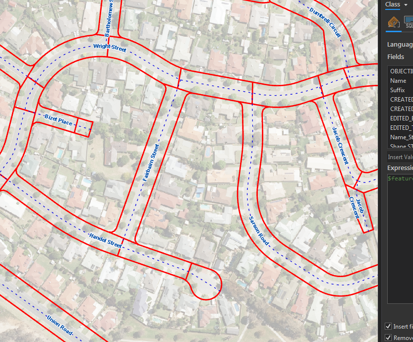
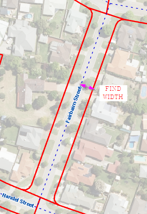
I know there will be some strange outputs no matter how I carry this out (court bowls etc), but as a starting point if I could use my road centreline, find perpendicular at the midpoint of the road centreline, and then extend outward until I intersect with a road outline, and return that distance, this would get me a result in the majority of cases.
Any rough ideas on how this could be achieved?
Cheers
Solved! Go to Solution.
- Mark as New
- Bookmark
- Subscribe
- Mute
- Subscribe to RSS Feed
- Permalink
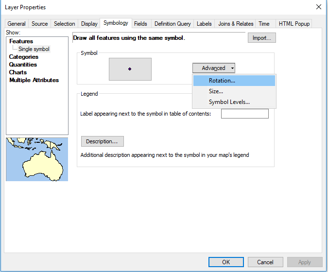
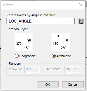
The angles created by the Linear Referencing layer are Arithmetic Bearings, not Geographic Bearings. Geographic Bearings start with 0 degrees pointing North and the degrees increase in a clockwise direction, but Arithmetic Bearings start with 0 degrees pointing East and the degrees increase in a counterclockwise direction. You have your layer set to show Geographic Bearings and need to change it to show Arithmetic Bearings. Change the setting on the Symbology tab by pressing the Advanced button and choosing the Rotation... option. Then choose your angle field and the Arithmetic Rotation Style and press OK for all the dialogs.
 \
\
Anyway, I just noticed that the Bearing Distance to Line tool expects degrees to be Geographic Bearings. To convert Arithmetic Bearings to Geographic Bearings create a new double field and use this Python calculation (where %LOC_ANGLE% is the Arithmetic angle field you want to convert):
(450 - %LOC_ANGLE%) % 360
I am sorry for the numerous steps needed just to convert the outputs of one tool for use as an input for another tool. The Geoprocessing Tool approach tends to run into these kinds of issues where the tools don't easily integrate with each other. A Python script could streamline the process and eliminate several steps, but my instructions are just meant to get the job done. Once the process is proven to work you can invest time in learning ways to optimizing the steps if you will need to do this process repeatedly.
- Mark as New
- Bookmark
- Subscribe
- Mute
- Subscribe to RSS Feed
- Permalink
I wanted to mention that the bearing conversion Python formula I gave works both to convert from Geographic bearings to Arithmetic bearings and vice versa. (%LOC_ANGLE% is the angle field or value you want to convert)
(450 - %LOC_ANGLE%) % 360
Also, you can get the complimentary angle of any angle in either bearing system with the Python formula:
(180 + %LOC_ANGLE%) % 360
- Mark as New
- Bookmark
- Subscribe
- Mute
- Subscribe to RSS Feed
- Permalink
When you use the Make Route Event Layer, you should actually not use the Offset field option (I mistakenly used it in the screenshot). You want the points to have no offset so that they will fall on the midpoint of the line directly. The offset_dist field was created to be used with the Bearing Distance to Line tool to create lines that extend from the centerline outward across the casing boundaries.
- Mark as New
- Bookmark
- Subscribe
- Mute
- Subscribe to RSS Feed
- Permalink
The output of step 10 should be a table, because the Bearing Distance to Line tool in Step 11 expects a table as its main input.
- « Previous
-
- 1
- 2
- Next »
- « Previous
-
- 1
- 2
- Next »