- Home
- :
- All Communities
- :
- Products
- :
- 3D
- :
- 3D Questions
- :
- Re: extrude between fail
- Subscribe to RSS Feed
- Mark Topic as New
- Mark Topic as Read
- Float this Topic for Current User
- Bookmark
- Subscribe
- Mute
- Printer Friendly Page
- Mark as New
- Bookmark
- Subscribe
- Mute
- Subscribe to RSS Feed
- Permalink
Hi all,
I don't know what I'm doing wrong here but a seemingly simple operation has resulted in wrong outcome.
I am trying to create an extruded feature between two tins. I have a Tin constructed with four points for the top and a tin with four points for the bottom. simple. then I constructed the tin domain and used tha in the extrude between tool. the resulting multipatch is an extrude square with flat top and bottom; set at the minimum distance between the tins. ie the feature is extruded between the highest elevation of the lower tin and the lowest elevation of the top tin.
I must have tried everything by now (triangulated domain, using the break lines of the tins as polygons) but nothing works.
There must be something simple I am missing here. Anyone know what it is?
Thanks a bunch
Victor
Solved! Go to Solution.
Accepted Solutions
- Mark as New
- Bookmark
- Subscribe
- Mute
- Subscribe to RSS Feed
- Permalink
Hello everyone,
The issue described in this post has been reported and is being dealt with as a bug in the program. ESRI is apparently working on it so it will be available again in a new release. In the mean time I'll see if I can perform the same task in a 3d modelling program. As soon as I here more about it I'll post it here.
Thanks for the replies!
Victor
- Mark as New
- Bookmark
- Subscribe
- Mute
- Subscribe to RSS Feed
- Permalink
Can you share the error message you've received?
- Mark as New
- Bookmark
- Subscribe
- Mute
- Subscribe to RSS Feed
- Permalink
Hi Khalid,
The thing is I get no error message at all, it says it succeeded the extrusion...
Victor
- Mark as New
- Bookmark
- Subscribe
- Mute
- Subscribe to RSS Feed
- Permalink
What do the 2 tins look like? I am trying to imagine how CreateTin makes a tin from only 4 points?
- Mark as New
- Bookmark
- Subscribe
- Mute
- Subscribe to RSS Feed
- Permalink
Creation of tins is done using a Delauny triangulation, using four points this results in two triangles (think of a piece of paper slightly folded along one diagonal). in the attachment there are three tins, each made from four points, left seen from the top, right birds eye view.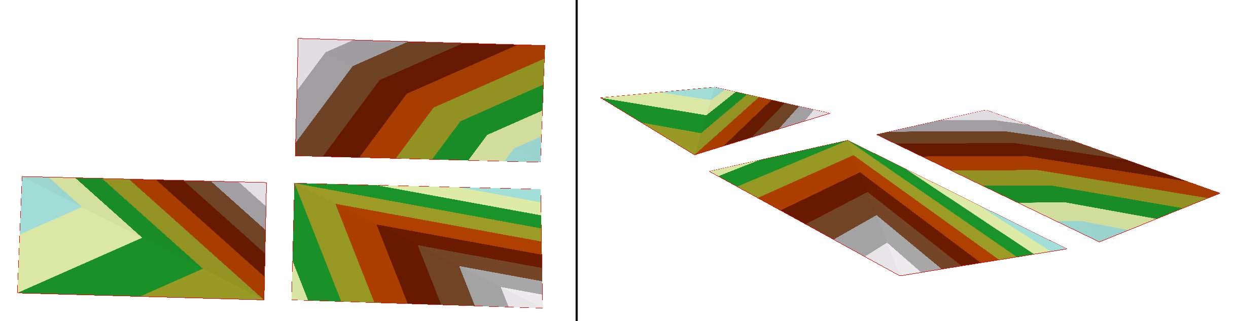
- Mark as New
- Bookmark
- Subscribe
- Mute
- Subscribe to RSS Feed
- Permalink
Thanks for posting. There are 3 tins here. Is there another set which is vertically above or below these ones?
Don't forget that Extrude between can only extrude the portion where both top and bottom overlap.
- Mark as New
- Bookmark
- Subscribe
- Mute
- Subscribe to RSS Feed
- Permalink
Yes, I have on another occasion used these tins for an extrusion with a top and bottom tin, this was simply an example of the shape of the four-point-tins.
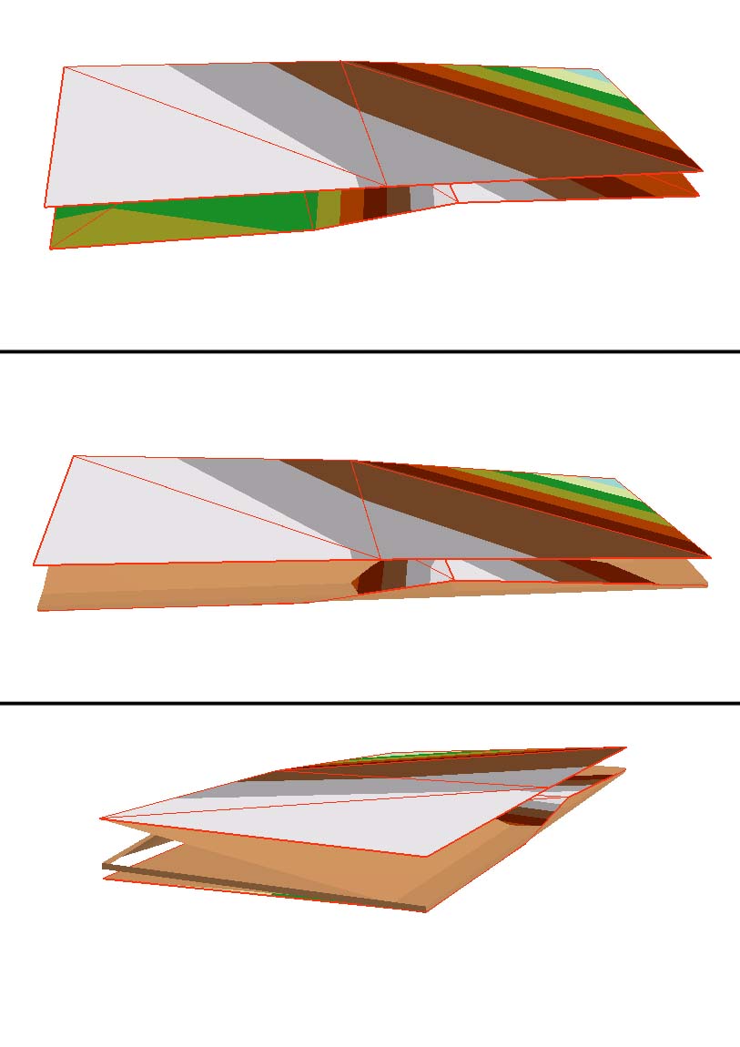
For the extrusion that failed recently I have used similarly shaped tins on the same location but one as top and one as bottom tin. The problem is that the extruded feature does not take on the shape of the tins but becomes a simplified squarish shape. I have attached an image, made up of three screenshots. The top is a view of the two tins on top of each other. the second is the tins with the wrongly extruded multipatch (pale orange), the lowest one is also the two tins with multipatch but now seen from a different angle. Notice how the multipatch is constructed with holes in it...
Cheers,
Victor
- Mark as New
- Bookmark
- Subscribe
- Mute
- Subscribe to RSS Feed
- Permalink
Can you try applying a slight buffer to the TIN domain output, then using the buffered polygon as your input to Extrude Between? If this works, then you ran into a rarely encountered known issue that occurs along certain coincident boundary conditions.
- Mark as New
- Bookmark
- Subscribe
- Mute
- Subscribe to RSS Feed
- Permalink
Thanks for you reply Khalid, I tried the process again but now with a buffered polygon but it unfortunately yielded the same results. Any other ideas? I'll see if I can contact ESRI directly as well, if there's a solution there I'll post it here.
Victor
- Mark as New
- Bookmark
- Subscribe
- Mute
- Subscribe to RSS Feed
- Permalink
Would you mind sharing the data by posting the XYZ coordinates? I couldn't reproduce the issue with an arbitrary set of 4 nodes per TIN.
Regards,
Khalid H. Duri
3D Analyst Product Engineer
Esri | 909.793.2853 x2747