Aligning 3D Street Furniture to Street Networks
- Subscribe to RSS Feed
- Mark as New
- Mark as Read
- Bookmark
- Subscribe
- Printer Friendly Page
Agencies abound have collected geolocated data on existing assets.... Whether the data is Point, Line, or Polygon in nature this data can be leveraged to rapidly generate 3D Model representations of Place. Often, this data lacks directional information required to accurately rotate models to the appropriate position. The easiest way to solve this is leveraging centralized features to detect directional alignment.
This post will cover the simplest example of feature alignment.
Obtaining directional information for street assets (points) leveraging street center-lines.
** The following Point-Data and Street Data were obtained from LiDAR for PeachTree Corners GA by CH2M Hill**
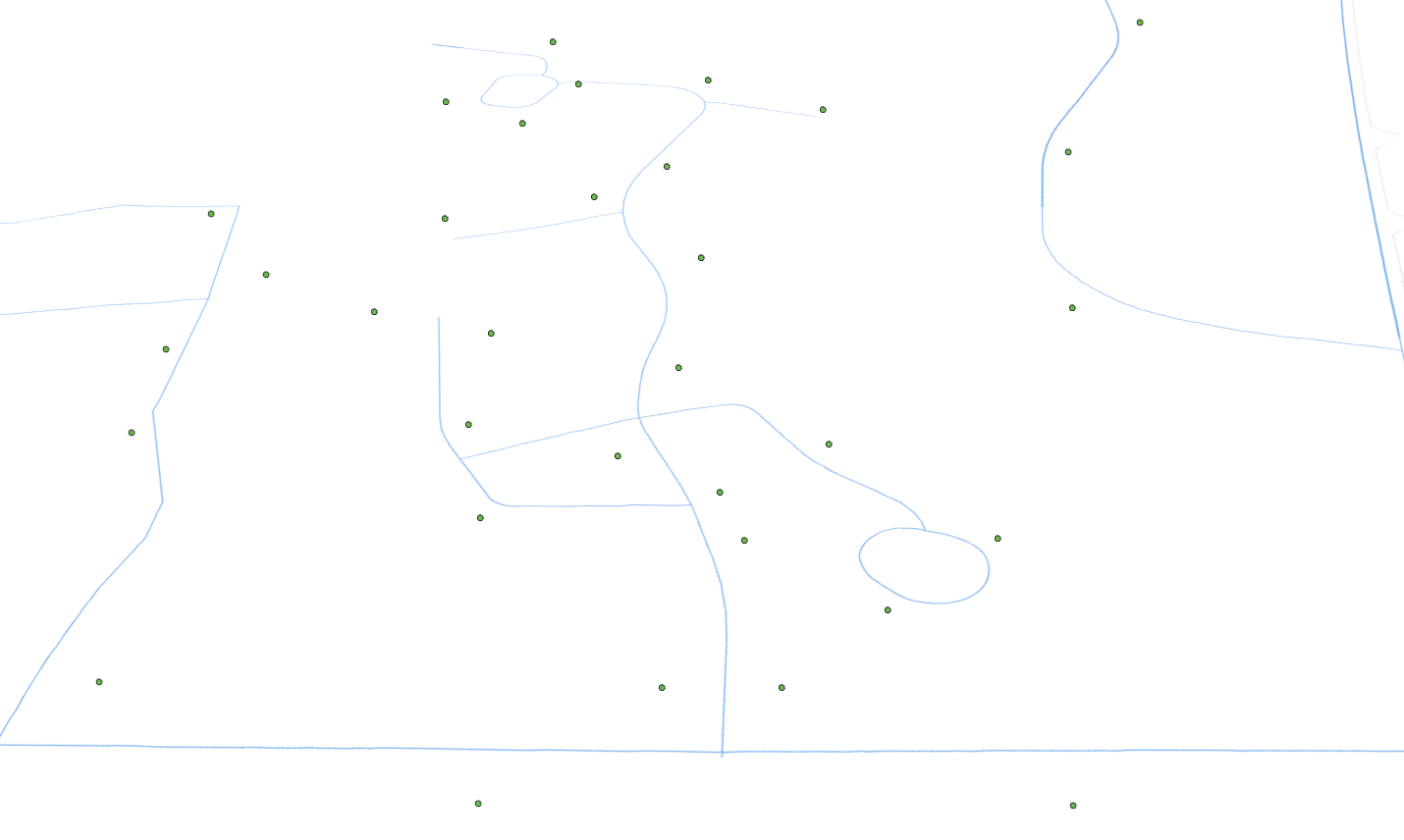
Obtaining directional information from street center-lines is as easy as running the "Near GP tool"

Just enter the following:
- Street asset point data as "Input Feature"
- Street-Centerline polygon as the "Near Feature"
- Apply a search radius of your liking you fill will encompass the full width of the largest street and street furniture
- Enable "Location" and "Angle" to be calculated
- Use default "Planar" Method for calculation.
In python this operation resembles:
import arcpy
inputPoints = r'MyPointFeature'
inputCenterlines = r'MyCenterlinePoly'
arcpy.analysis.Near(inputPoints, inputCenterlines, "100 Feet", "LOCATION", "ANGLE", "PLANAR")
The resulting calculations are parsed into the points featureclass as:
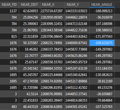
Delete fields
- NEAR_FID, NEAR_DIST, NEAR_X, NEAR_Y
- This only leaves NEAR_ANGLE
Use the "AlterField" GP tool to change the filed called "NEAR_ANGLE" to direction.
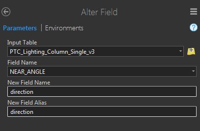
In python this operation resembles:
arcpy.AlterField_management(inputPoints, "NEAR_ANGLE", "direction", None, "DOUBLE", 8, "NULLABLE", True)\
Your final table update should resemble something similar to the following:

Also use the "Add Field" GP tool to add a a field called "Height" and "Calculate Field" GP tool to apply a generic height to all points. You can update with accurate heights in the future or parse existing height data to the field if available.
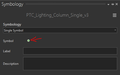
Next Highlight your point features in the "Contents" Panel
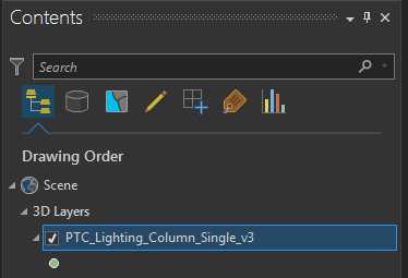
On the right Side Panel select "Symbology" to open the Symbology Options:
Select the Symbol Icon
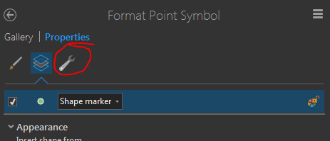
Select the "Structure Icon.... It resembles a wrench
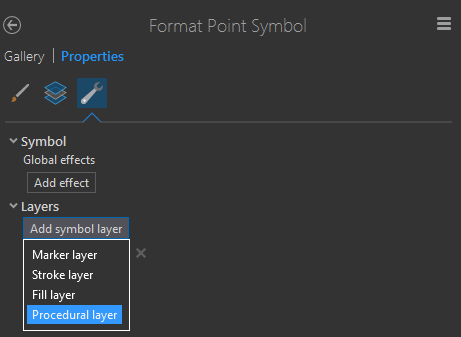
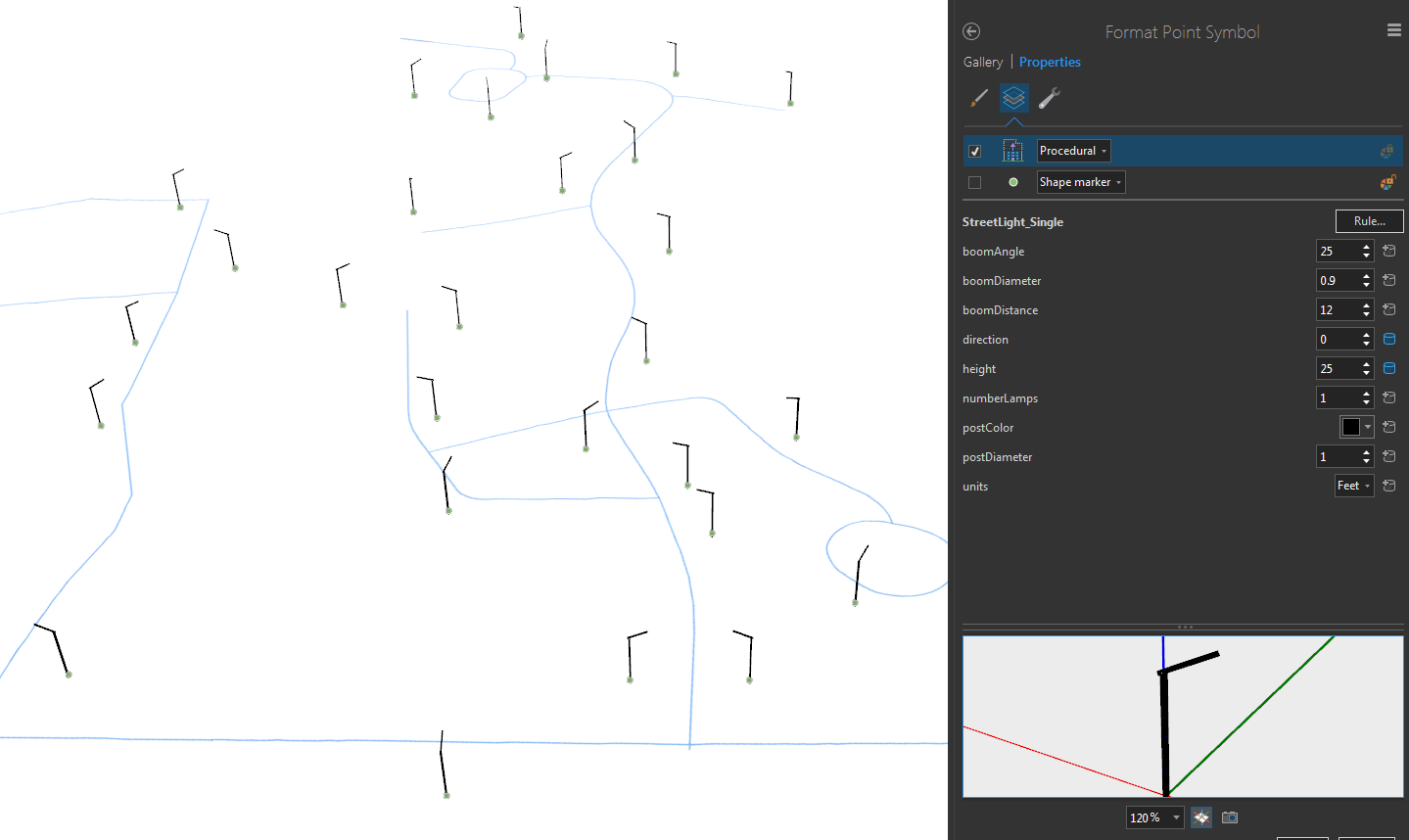
Select "Add Symbol Layer" and choose "Procedural Layer"
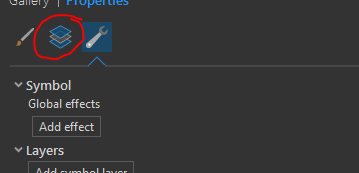
Click the "Layers" Icon
Choose to "Add a Procedural Rule"

Apply the "StreetLight_Single.rpk" CityEngine Rule Package file.
You can find the .rpk file as a attachment to this blog post.
The results should resemble the following:
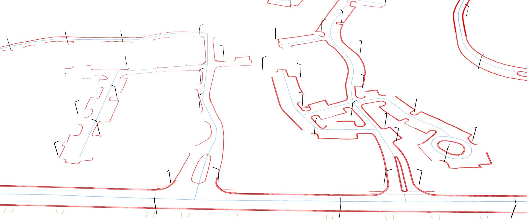
You can then view the rule in context to other data you may have.
If you want to add the 3D Models to ArcGIS Online workflow:
- Features from CityEngine rules GP tool.
- Create Scene Layer Package
- Share Package
The Rule Package you just applied to the point data leverages what is called CGA Shape Grammar. To program and edit such .rpk files requires a CityEngine Basic License.
You can download a 30 Day free trial of CityEngine here: Esri CityEngine | 3D Modeling Software for Urban Environments
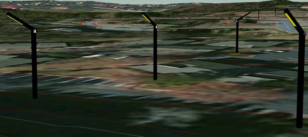
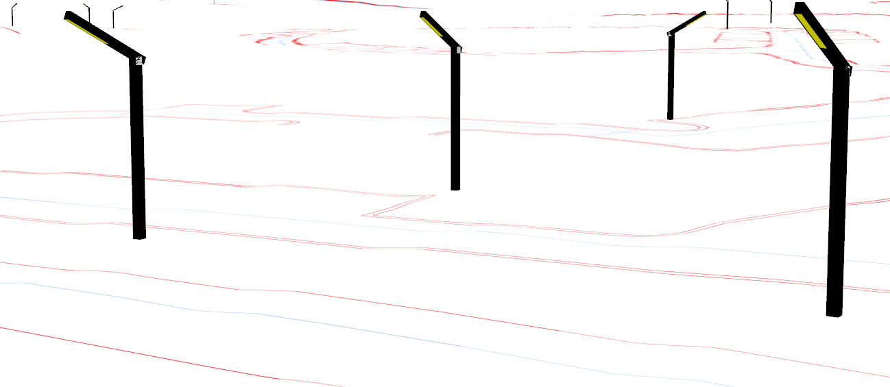
Here is the code to generate the completely procedural light post above.
/**
* File: LampPost.cga
* Created: 6 Mar 2017 15:33:53 GMT
* Author: Esri
*/
version "2016.1"
attr height = 25
attr direction = 0
attr postDiameter = 1
attr boomDiameter = 0.9
attr boomDistance = 12
attr boomAngle = 25
attr numberLamps = 1
@Range("Feet","Meter")
attr units = "Feet"
@Color
attr postColor = "#000000"
unitConv =
case units == "Feet": 0.3048
else: 1
directionMod =
case direction > 0: direction + 90
else: direction + 90
@InPoint
@StartRule
basePost-->
alignScopeToAxes(y)
primitiveCube()
s(postDiameter*unitConv, height*unitConv, postDiameter*unitConv)
#s('1,height*unitConv,'1)
rotate(rel, world, 0, directionMod, 0)
center(xz)
upperConnector
upperConnector-->
split(y){(height*unitConv) - (boomDiameter*unitConv): colorPost | ~1: upperConnectorStart}
upperConnectorStart-->
comp(f){
top: colorPost |
bottom: NIL |
front: lightBoomGeom1 colorPost |
back: colorPost X. |
left: colorPost X. |
right: colorPost X.
}
lightBoomGeom1-->
alignScopeToAxes(y)
t(0,0,-(boomDiameter/2))
r(scopeCenter, - boomAngle, 0, 0)
#rotate(abs, object, 0, 0, 90)
lightBoomGeom
lightBoomGeom-->
split(x){(postDiameter-boomDiameter)/2: colorPost | ~1: lightBoom | (postDiameter-boomDiameter)/2: colorPost}
lightBoom-->
extrude(boomDistance*unitConv)
lightBoom_lamp
lightBoom_lamp-->
rotateScope(45, 0, 0)
rotateScope(0, 0, 45)
split(y){(boomDistance*.4)*unitConv: colorPost |(boomDistance*.6)*unitConv: lamp}
lamp-->
alignScopeToAxes(y)
comp(f){
top: colorPost |
bottom: insetLamp |
front: colorPost|
back: colorPost |
left: colorPost |
right: colorPost
}
insetLamp-->
offset(-0.1*unitConv) A
A-->
comp(f) { inside: light | border: colorPost }
light-->
color("#FFFF00")
colorPost-->
color(postColor)
You must be a registered user to add a comment. If you've already registered, sign in. Otherwise, register and sign in.