- Home
- :
- All Communities
- :
- Products
- :
- ArcGIS CityEngine
- :
- ArcGIS CityEngine Questions
- :
- Is it possible to rotate a object to the orientati...
- Subscribe to RSS Feed
- Mark Topic as New
- Mark Topic as Read
- Float this Topic for Current User
- Bookmark
- Subscribe
- Mute
- Printer Friendly Page
Is it possible to rotate a object to the orientation of a polygon with cga
- Mark as New
- Bookmark
- Subscribe
- Mute
- Subscribe to RSS Feed
- Permalink
I am working on a project where the goal is to symbolize a power line network in 3D. My idea is to write a .cga-rule, which I’m “converting” to a .rpk and use this .rpk as a procedural fill symbol on a polygon layer (since line geometry is not supported for procedural fill) in arcgis pro.
I have written the .cga rule, but I have hit some bumps on the road:
- Is there possible to write in the code, so the split function follows the direction of the source (the polygon).?
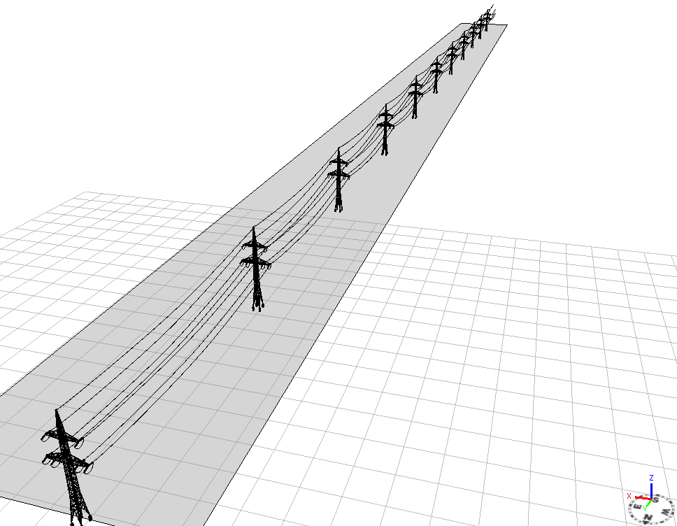
Figur 1 Here you see the rule where the split(x){~avstand: alignScopeToGeometry(zUp,0) lagHoyspent}* is active. It works perfect if the polygon is orientated in the y-direction and the split is set to ~x*.
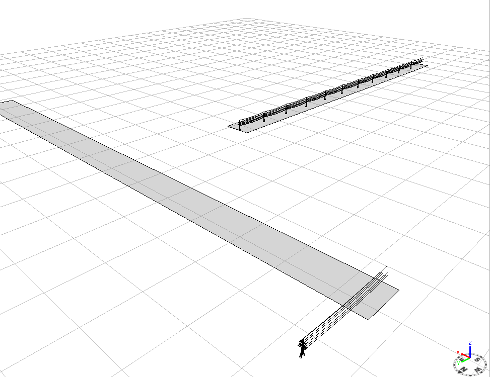
Figur 2: And here we see the same rule on a polygon orientated along the x axis.
Thank you all for looking in to this
Kind regards
Jørn
Solved! Go to Solution.
Accepted Solutions
- Mark as New
- Bookmark
- Subscribe
- Mute
- Subscribe to RSS Feed
- Permalink
In your version you seem to align the scope to longest and then immediately change it in the next line, so I'd try moving the align to longest so it comes after the other alignScope.... like this:
@StartRule
trase -->
split(x){~avstand: alignScopeToGeometry(yUp,0) lagHoyspent}*
lagHoyspent -->
alignScopeToGeometry(yUp, any, longest)
.....
- Mark as New
- Bookmark
- Subscribe
- Mute
- Subscribe to RSS Feed
- Permalink
Hi Jørn.
One solution would be to align the scope to the longest edge using alignScopeToGeometry(). This will align the x axis with the longest edge (of the largest face), and you can do your split in x as before. For the first parameter, you can pick y or z to be the axis that goes upwards (along the face normal).
alignScopeToGeometry(yUp, any, longest)
See the help documentation for a description of the possible parameters.
- Mark as New
- Bookmark
- Subscribe
- Mute
- Subscribe to RSS Feed
- Permalink
Hi Cheryl,
Thank you for your answer. How ewer I still canot figure out how this alignScopeToGeometry() is working:
Here is some of my rule now:
@InPolygon
@StartRule
trase -->
alignScopeToGeometry(yUp, any, longest)
split(x){~avstand: alignScopeToGeometry(yUp,0) lagHoyspent}*
lagHoyspent -->
extrude(hoyde)
center(xz)
r(0,0,0)
t(0,0,0)
s(bredde, hoyde, avstand)
i(poleAsset)
color (farge)
And this results in: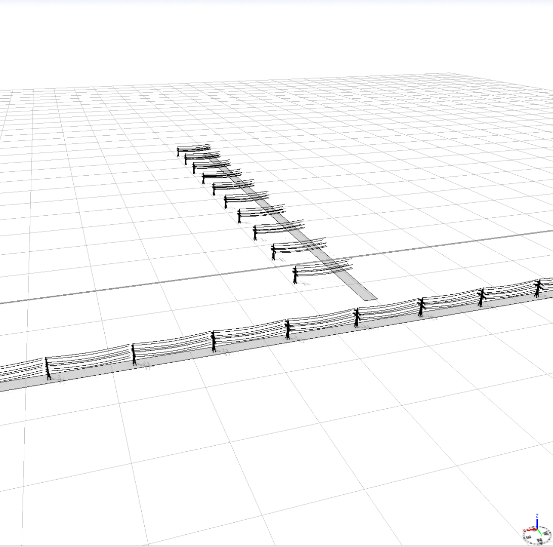
What am I missing here ? 
Thank you!
Regards
Jørn
- Mark as New
- Bookmark
- Subscribe
- Mute
- Subscribe to RSS Feed
- Permalink
In your version you seem to align the scope to longest and then immediately change it in the next line, so I'd try moving the align to longest so it comes after the other alignScope.... like this:
@StartRule
trase -->
split(x){~avstand: alignScopeToGeometry(yUp,0) lagHoyspent}*
lagHoyspent -->
alignScopeToGeometry(yUp, any, longest)
.....
- Mark as New
- Bookmark
- Subscribe
- Mute
- Subscribe to RSS Feed
- Permalink
Hi Ben,
This works like a charm, thanks.
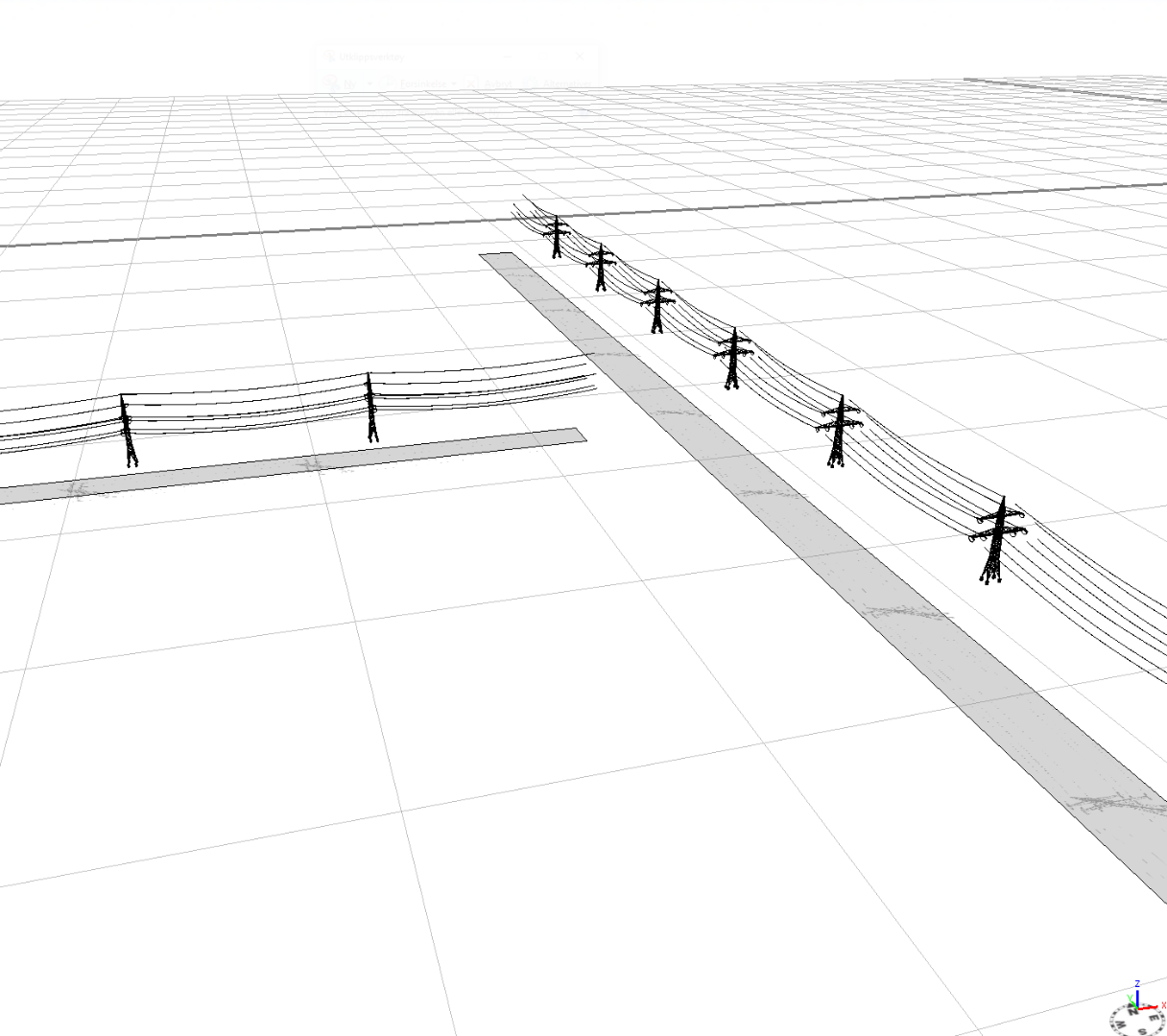
Do you know if its possible to center the object to the polygon (without manually adjust by using the t() ) , because now my power line is floating in the air and it is not centered to the source polygon?
Regards
Jørn
- Mark as New
- Bookmark
- Subscribe
- Mute
- Subscribe to RSS Feed
- Permalink
I'm not sure....... but I don't see why you are using extrude() - I'd try removing it, and possibly the center(xz) line as well.
- Mark as New
- Bookmark
- Subscribe
- Mute
- Subscribe to RSS Feed
- Permalink
Hmm, what was I thinking 
This solved the case, thanks alot!
Regards
Jørn
- Mark as New
- Bookmark
- Subscribe
- Mute
- Subscribe to RSS Feed
- Permalink
Hi Jørn.
To better understand what alignScopeToGeometry() is doing, you can use the Model Hierarchy (Window -> Show Model Hierarchy). This let you see the scope axis for your objects at each level in the rules. Click on your model in the scene, and then click on the "Inspect Model" button (2nd button to the right of the "Generate" button on the toolbar along the top). Then a tree shows up in the Model Hierarchy window. It starts with your root node (trase), and the next level of the tree is the rule lagHoyspent. Click on this level to see how the scope is positioned when you call this rule (right before the rule is executed, after the split). On the model, the x axis is drawn in red, y is green, and z is blue. The last level in the tree shows how the scope is positioned after the rule lagHoyspent is completely exectued. alignScopeToGeometry(yUp, any, longest) aligns the x axis to the longest edge.
Hopefully, the Model Hierarchy would help you understand what was going on with the translation problem as well.
I'm glad you found a solution (Ben, thanks for the solution!). Be careful though because it might work differently for both cases of polygons where (a) the short side of the polygon is larger than avstand or (b) the short side of the polygon is smaller than avstand. Perhaps you don't need to care about both cases though.
Another solution would be to align the x axis to the longest edge of your polygon, then split in x, and then without realigning the scope, just resize the scope and insert the object.
@StartRule
trase -->
alignScopeToGeometry(yUp, any, longest)
split(x){~avstand: lagHoyspent}*
lagHoyspent -->
s('1, hoyde, bredde) // the scope size in the x dir will be avstand from the split
center(z)
i(poleAsset)
color (farge)
- Mark as New
- Bookmark
- Subscribe
- Mute
- Subscribe to RSS Feed
- Permalink
Thanks Cheryl, this was helpful!
This Model Hierarchy window is such a great “tool” for debugging your .cga code!