- Home
- :
- All Communities
- :
- Products
- :
- ArcGIS Utility Network
- :
- ArcGIS Utility Network Questions
- :
- Distance trace - how to?
- Subscribe to RSS Feed
- Mark Topic as New
- Mark Topic as Read
- Float this Topic for Current User
- Bookmark
- Subscribe
- Mute
- Printer Friendly Page
- Mark as New
- Bookmark
- Subscribe
- Mute
- Subscribe to RSS Feed
- Permalink
- Report Inappropriate Content
Hello,
I am trying to figure out how to do a distance trace in the Utility Network. I want to trace a line starting from a specific device (trace location), the trace should stop after a given distance. I want to find out exactly where this distance point is on the traced route. The route may well belong to different tiers and have branches.
I have searched this community in vain and also consulted various Esri videos on the subject of network tracing (including this one: Trace Operations in the Trace Network). My own attempts with the Electric Utility Network Foundation Solution data have also been unsuccessful so far.
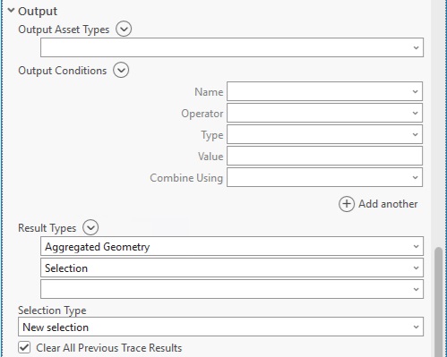
What I think I have understood so far is that you have to define the distance via a Function Barrier with "Add - Shape.Length" (or any other lenght attribute) and use the "Aggregated Geometry" option as the Output Result Type in order to be able to visualize the exact distance position on the map. Unfortunately, I have not been able to do this in all my attempts, and depending on the choice of trace location, various errors have occurred when executing the network trace.
Is there a detailed description somewhere, or better still a video, that shows how to formulate the trace in order to find the desired distance position on the route?
I would be very grateful for any hints or help.
Best regards,
Jürgen
Solved! Go to Solution.
Accepted Solutions
- Mark as New
- Bookmark
- Subscribe
- Mute
- Subscribe to RSS Feed
- Permalink
- Report Inappropriate Content
You can find an example of this here: https://mediaspace.esri.com/media/t/1_nl5m6g2p?st=1848:
If you are still having issues, please post the error message you are seeing.
- Mark as New
- Bookmark
- Subscribe
- Mute
- Subscribe to RSS Feed
- Permalink
- Report Inappropriate Content
You can find an example of this here: https://mediaspace.esri.com/media/t/1_nl5m6g2p?st=1848:
If you are still having issues, please post the error message you are seeing.
- Mark as New
- Bookmark
- Subscribe
- Mute
- Subscribe to RSS Feed
- Permalink
- Report Inappropriate Content
Hi Robert,
Thank you for pointing out this very interesting video. Unfortunately, it didn't help me with my problem. Although it is explained at the end of the video that, as I had assumed, in order to be able to identify the exact distance position X, the “Aggregated Geometry” option must be used as the Result Type, this has not worked so far in my attempts. (However, thanks to the video, I have not received any further error messages when trying again).
My test case looks like this: I select any mid-voltage transformer (of the Electric Utility Network Foundation Solution) and define the primary terminal as the trace location. Then I execute an upstream trace in the distribution tier with the following filter function barrier: Add - Shape length - Is greater than or equal to - 20 (so my distance position is 20 units). Before running the trace I have deleted the traversability barriers of the trace configuration. My output options are “Aggregated Geometry” and “Selection”.
In fact, the trace delivers a result - it selects the line connected upstream to the transformer and generates an aggregated line geometry. However, this is not 20 units long, but goes as far as the vertex of the line that most closely fulfills the function barrier condition. However, I would have expected the aggregated geometry to be exactly 20 units long.
On further attempts with other X values (50, 100, 200), it can be seen that the aggregated geometry always runs up to a vertex of the line, but never ends at the exact X value.
I am now wondering whether I am doing something wrong here, or whether it generally does not work to determine the exact distance position.
I would be happy to demonstrate my test case in a web session.
Best regards, Jürgen
- Mark as New
- Bookmark
- Subscribe
- Mute
- Subscribe to RSS Feed
- Permalink
- Report Inappropriate Content
Can you reproduce the problem on the sample data included with the electric utility network foundation?
When I test this out, I see the trace correctly stop midspan within a line segment (i.e. it's not stopping at line vertices).

- Mark as New
- Bookmark
- Subscribe
- Mute
- Subscribe to RSS Feed
- Permalink
- Report Inappropriate Content
Hi Robert,
I would have expected the result of my trace to be as shown in your screenshot.
Here are the parameters and a few screenshots of my test case, which I can use to reproduce my observations at any time.
ArcGIS Enterprise: 11.1
ArcGIS Pro: 3.1.3
Trace Location: Electric Device - Medium Voltage Transformer - Overhead Single Phase - MV->LV - MV-XFR-12 (Object ID 1387) - 2wXFR:Primary
Trace parameter: Upstream trace with filter barrier at distance 50 units (no other barriers)
The result is the same with a distance value of 20 or 100 (UpstreamTraceResult50.jpg). With a distance value of 110 the result changes, the aggregated line geometry now goes to the next vertex (UpstreamTraceResult110.jpg).
Perhaps you can use this information to try to recreate my test case. If you get a different result than me, we can also have a look at the test on my system.
Many thanks and best regards,
Juergen
- Mark as New
- Bookmark
- Subscribe
- Mute
- Subscribe to RSS Feed
- Permalink
- Report Inappropriate Content
This appears to be a bug, please log a case with support.