Hello, I have a few questions. Received data from a contractor that I had to apply to an asset package and then create a Utility Network from that asset package. The linework that was provided only included conduits and not the actual circuits so I am now digitizing the circuits from the substation to visually show the connectivity from each circuit line starting at the source subnet controller. These circuits, in many places, share vaults and manholes which are set up to be structure junctions. I'd like the circuits to be connected to the vaults/manholes through association but not geometrically as there is inaccuracy in the cad drawing. How can this be done?
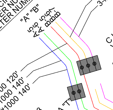
Furthermore, as I begin the digitizing of the circuits, these will be my subnet lines from each source/subnet controller at the substation. Would I digitize these as subnet lines or electrical lines? Or what would be the best workflow to ensure the digitized circuits show as both? Our goal is to simply run traces up or down stream in the network for when there are outages/planned construction or just to simply have a better understanding of the connected network as a whole.
New to utilities in general so this is a great learning curve to me. Have played around with the sample Naperville data but I'm in charge of setting the UN up for our electrical public utilities.
TYIA!