Hi everyone,
we are doing some testing on the gas utility network and we have a question regarding the "riser pipe" (MONTANTI in italian) objects which in reality are pipes going up vertically. At the moment in our gas system they are represented as points with the necessary attributes to know the measured length, altitude etc.
We have seen that on the gas solution (ArcGIS Solutions - GAS ) there is a line asset group which is called "Riser Pipe" with this description, "The Riser Pipe asset group in the PipeLine feature class represents the vertical pipe where a pipe system transitions from below ground to above ground. "
Our idea is therefore to transform the point objects we have today into linear objects "Riser Pipe" the problem is however that we do not know quite how to draw them.
- If they are located at the end of a utility branch pipe it is easy enough, we create a point object that connects the branch to the riser and then the riser to the utility
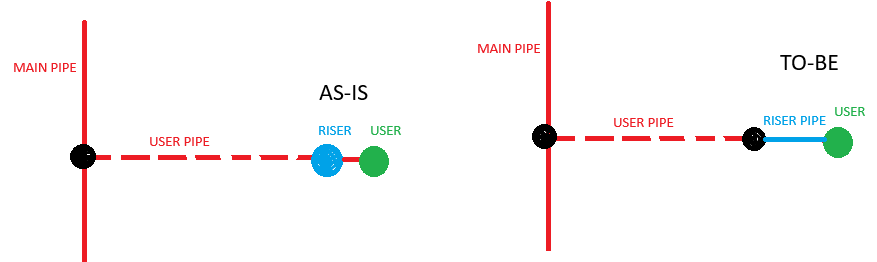
- But what if it is located between two pipes? the idea we had in order not to change the drawn lengths too much was to create a vertex of the sections and rotate it slightly and in between insert the riser connected to the two sections with a node. but in this case what node do we put (the black point as junction or device)? do you have any other ideas on how we could draw the riser in this case? any best practices?

Thank you