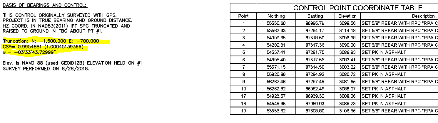
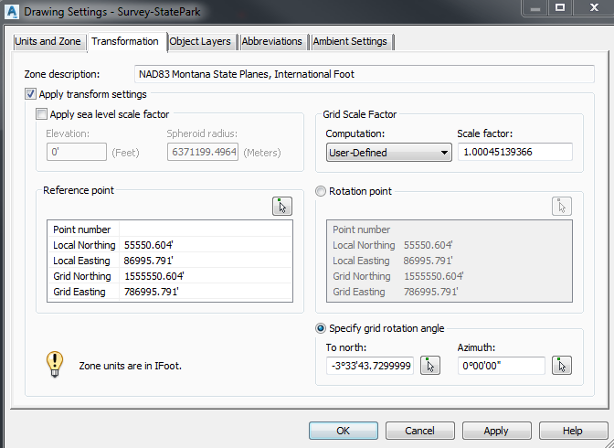
I need help figuring out how to get CAD data that has a shift, rotation and scale factor based on this projection. NAD_1983_StatePlane_Montana_FIPS_2500_Feet_Intl
WKID: 2256
Basically I have a drawing that is based on the above projection, but it has a coordinate truncation (shift), scale factor AND rotation set to the CAD .dwg provided.
Ordinarily, I would create a world file that could take 2 coordinate pairs and then that would georeference the CAD drawing. That worked when I simply had a coordinate shift. (often the engineers would truncate coordinates to make the designs space smaller in CAD)
Now I'm given data with a scale factor AND a rotation included with coordinate truncation.
How do I get this CAD drawing to reside in map projected space? What's the best way to do that?
Basically, I was provided a PDF control table and info as well as whatever they used to set the ground to grid translation in AutoCAD. (they gave a screen shot)
I think I can figure out the scale factor - but the rotation is problematic to me - I'm presuming it's rotating on the origin?
I want to add this CAD data to a map with other projected data so I can digitize data from it.
Any advice is appreciated.