Hi all.
We are using the import DXF function to create a street network for our project. We need to be quite precise about how the street network is generated and so can't draw this directly in CityEngine.
There are some limitations to how this works that are making this workflow difficult. Hoping I'm missing something and you can help me.
This is the street network, drawn in AutoCAD:
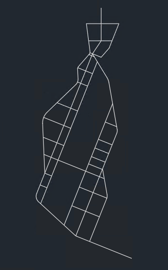
All lines are flattened (Z=0), and trimmed (ends of lines meet exactly). I'm using DXF version 2007 (also 2004, with the same results).
I've played around with various import options (including different settings for 'Cleanup Graph'), and have found the following issues:
1 - Streets don't join other streets at acute angles.
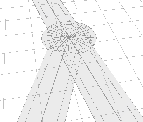
2 - Not possible to join more than 2 lines together at a node. See below - a corner is formed from 2 of the lines in the CAD file, but not the other line running through it.
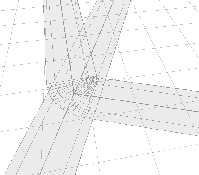
3 - Lines drawn perpendicular to one another - some join, some don't.
No join - not possible to fix this by dragging the node of the left road away and then rejoining with the street running up and down the image.
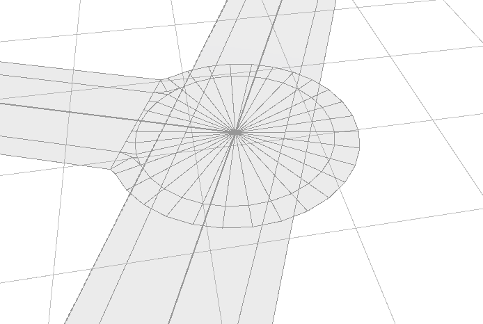
Join - drawn exactly the same way in CAD!
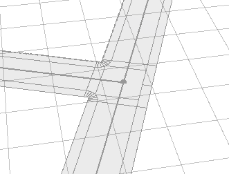
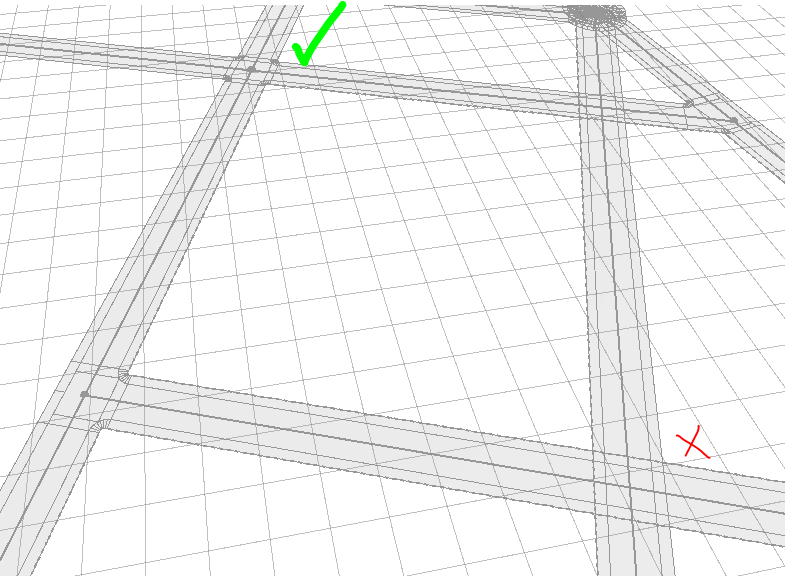
4 - Some streets intersect and create a node, some don't:
Correct intersection shown top left - incorrect bottom right. Again, these are drawn exactly the same way in CAD.
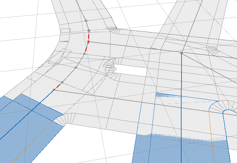
5 - Strange joins when lines meet arcs (shown in CAD vs. CityEngine)
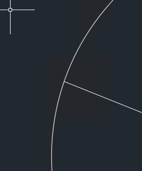
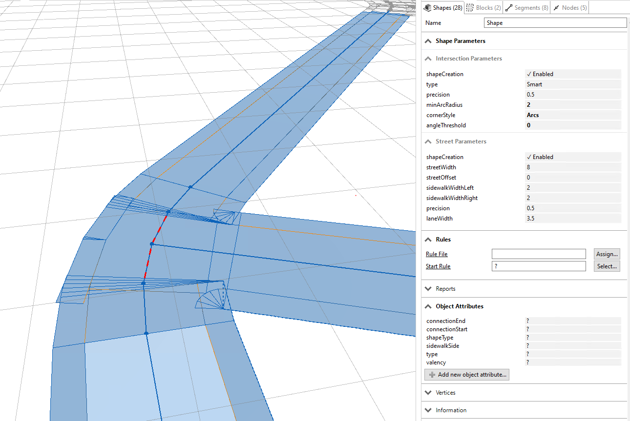

--
This is really fundamental stuff that may end up making it impossible to work in CityEngine for this project, which would be a real shame!
Does anyone have any pointers on how to address the issues above?
Any help much appreciated.