In a previous post the distance between a 3D tree and a static 3D overhead power line was calculated using the Near 3D tool (see: Creating a 3D tree with Arcpy for 3D Analysis ). However, I was told that the position of the cable is not static, and the movement of the cable due to wind could easily reach a movement of 20°. In some cases this will extent the 2D location of the overhead power line up to more than 20 meters causing a huge impact on the selection of trees that need to be logged for security reasons.
So, how could we model this movement? We could start with determining the straight line between the first and the last point of the overhead power line (grey line):
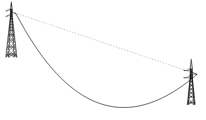
For each point on the 3D power line, we can determine the distance between the Z value of the point and the Z value on the straight line. This is the radius of the circle of movement. Using this distance and the cosine of the angle of movement we can determine the horizontal displacement of the point, which we should apply perpendicularly to the angle of the power line. For the difference in Z of the new point, we can use the sine of the angle of movement. When we append all these points to a list, we can create the 3D polyline of the power line at a certain angle of blowout.
See below the code used:
def main():
    import arcpy
    import math
    import os

    arcpy.env.overwriteOutput = True

    # input and output featureclasses
    fc = r'D:\Xander\Apoyo\SkyBlue\SanLorenzo\SanLorenzo3D.gdb\lineas_cables2'
    fc_out = r'D:\Xander\Apoyo\SkyBlue\SanLorenzo\SanLorenzo3D.gdb\conductor_balanceo_total_v01'

    # angles (degrees) of movement to be calculated
    lst_angulo_balanceo = [5, 10, 15, 20]

    # create output featureclass
    sr = arcpy.Describe(fc).spatialReference
    ws, fc_name = os.path.split(fc_out)
    arcpy.CreateFeatureclass_management(ws, fc_name, "POLYLINE", None, "DISABLED", "ENABLED", sr)

    # fields
    fld_oid ="ORI_OID"
    fld_type = "LineType"
    fld_angle = "Angle"
    fld_lr = "LeftRight"

    # add fields
    arcpy.AddField_management(fc_out, fld_oid, "LONG")
    arcpy.AddField_management(fc_out, fld_type, "TEXT", None, None, 25)
    arcpy.AddField_management(fc_out, fld_lr, "TEXT", None, None, 10)
    arcpy.AddField_management(fc_out, fld_angle, "DOUBLE")

    # open insert cursor
    with arcpy.da.InsertCursor(fc_out, ('SHAPE@', fld_oid, fld_type, fld_lr, fld_angle)) as curs_out:

        # loop through 3d overhead power lines
        with arcpy.da.SearchCursor(fc, ('SHAPE@', 'OID@')) as curs:
            for row in curs:
                polyline = row[0]
                oid = row[1]

                # store input 3D power line
                curs_out.insertRow((polyline, oid, 'Overhead Power line 3D', 'Center', 0.0, ))

                # create 3D straight line between towers
                pnt1 = polyline.firstPoint
                pnt2 = polyline.lastPoint
                straight_3d = arcpy.Polyline(arcpy.Array([pnt1, pnt2]), sr, True, False)
                curs_out.insertRow((straight_3d, oid, 'Straight line 3D', 'Center', 0.0, ))

                # get 2D angle of power line and perpendicular angles
                pntg1 = arcpy.PointGeometry(pnt1, sr)
                pntg2 = arcpy.PointGeometry(pnt2, sr)
                angle_line = getAngle(pntg1, pntg2)
                angle_2d_l = angle_line + 90
                angle_2d_r = angle_line - 90

                # loop through movement angles to be calculated
                for angulo_balanceo in lst_angulo_balanceo:

                    # list vertices of 3D polyline (left and right)
                    lst_vertices_l = []
                    lst_vertices_r = []
                    cnt = 0

                    for part in polyline:
                        for pnt_3d in part:
                            cnt += 1

                            # determine each position on the 2D line (fraction)
                            pos_percentage = straight_3d.measureOnLine(pnt_3d, True)

                            # determine z value of point on straight 3D line between towers
                            z_straight = (pnt2.Z - pnt1.Z) * pos_percentage + pnt1.Z

                            # difference of point between 3D power line and straight line
                            z_dif = z_straight - pnt_3d.Z

                            # horizontal displacement (cos)
                            inv_angulo_balanceo = 90 - angulo_balanceo
                            inv_ang_pi = float(inv_angulo_balanceo) / 180.0 * math.pi
                            dist_hor = z_dif * math.cos(inv_ang_pi)

                            # create 2d point (left and right) based on horizontal displacement
                            pntg_3d = arcpy.PointGeometry(pnt_3d, sr, True, False)
                            pnt_xy_l = pntg_3d.pointFromAngleAndDistance(angle_2d_l, dist_hor, 'PLANAR')
                            pnt_xy_r = pntg_3d.pointFromAngleAndDistance(angle_2d_r, dist_hor, 'PLANAR')

                            # vertical displacement (sin)
                            dist_ver = z_dif * math.sin(inv_ang_pi)
                            z = z_straight - dist_ver

                            # create 3D point left and right and add to lists
                            pnt_new_l = arcpy.Point(pnt_xy_l.firstPoint.X, pnt_xy_l.firstPoint.Y, z)
                            lst_vertices_l.append(pnt_new_l)
                            pnt_new_r = arcpy.Point(pnt_xy_r.firstPoint.X, pnt_xy_r.firstPoint.Y, z)
                            lst_vertices_r.append(pnt_new_r)

                    # create polyline left and insert
                    polyline_new_l = arcpy.Polyline(arcpy.Array(lst_vertices_l), sr, True, False)
                    curs_out.insertRow((polyline_new_l, oid, 'Balanceo', 'Left', angulo_balanceo, ))

                    # create polyline right and insert
                    polyline_new_r = arcpy.Polyline(arcpy.Array(lst_vertices_r), sr, True, False)
                    curs_out.insertRow((polyline_new_r, oid, 'Balanceo', 'Right', angulo_balanceo, ))


def getAngle(pntg1, pntg2):
    '''determine angle of line based on start and end points geometries'''
    return pntg1.angleAndDistanceTo(pntg2, method='PLANAR')[0]


if __name__ == '__main__':
    main()
And the result obtained:
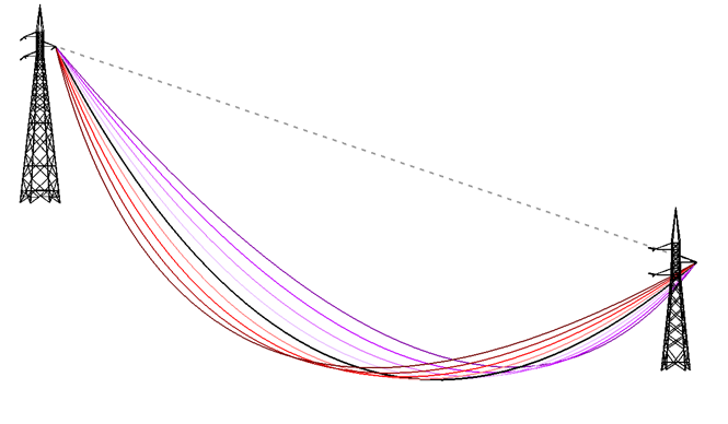
This is the situation for a very strong force of wind (occurrence every 50 years).
Python python snippets3D