- Home
- :
- All Communities
- :
- Products
- :
- ArcGIS Pro
- :
- ArcGIS Pro Questions
- :
- CAD file(dwg) import into ArcGIS Pro
- Subscribe to RSS Feed
- Mark Topic as New
- Mark Topic as Read
- Float this Topic for Current User
- Bookmark
- Subscribe
- Mute
- Printer Friendly Page
- Mark as New
- Bookmark
- Subscribe
- Mute
- Subscribe to RSS Feed
- Permalink
- Report Inappropriate Content
Hello! I am trying to import a CAD file which is in OS (OSGB36 coordinate system) into ArcGIS Pro. I could set the OSGB36 coordinate system (UK) for the database and for the base map(in the map properties) as well, but I cannot see my CAD objects when I import them into ArcGIS Pro. Also I cannot set the OSGB36 coordinates on the main map layout where the cursor coordinate visible. Could you help me what is the correct workflow for import a CAD file which is not in WGS84 or how can I set my project into another coordinate system? Many thanks
UPDATE: CAD file attached.
Solved! Go to Solution.
Accepted Solutions
- Mark as New
- Bookmark
- Subscribe
- Mute
- Subscribe to RSS Feed
- Permalink
- Report Inappropriate Content
I downloaded your dwg and took a look. The dwg loads fine for me (Pro 2.3). The problem is the CAD file is not in OSGB36.
OSGB36 is a geographic coordinate system; so the coordinates are decimal degrees (geographic) coordinates. Those coordinates in the DWG are certainly not OSGB36 because they are clearly in a projected coordinate system, that is, in meters or feet, not degrees. To have things plot in the right place (since your dwg file has no coordinate system defined) you need to find out what the xy coordinates are, and set the map coordinate system to it. If the coordinate system you set for the map matches the cad file's xy values, the basemap will appear to line up under your CAD linework.
You may want to check this out again too, but you definitely are stuck until you find out what the XY coordinates in your DWG file are.
Map units, location units, and display units—ArcGIS Pro | ArcGIS Desktop
I hope this is helpful.
- Mark as New
- Bookmark
- Subscribe
- Mute
- Subscribe to RSS Feed
- Permalink
- Report Inappropriate Content
I suggest zooming to the CAD layer and if the data comes up, see if it is the correct shape. If so, then look at the map's extent, it should be obvious if the cad file coordinates are really in inches, or shifted. If so, you may need to the georeference the CAD file with a shift and scale using some known control points.
- Mark as New
- Bookmark
- Subscribe
- Mute
- Subscribe to RSS Feed
- Permalink
- Report Inappropriate Content
Hi Curtis,
Thank you for your comment. I have tried zooming, but nothing. The data is not there. The CAD drawing in meter and this is what I want. I may calculate some coordinates which is well known in WGS and OSGB36 but should have a simpler solution as I can set the OSGB36 as a coordinate system in ArcGIS Pro. My feeling that I make something wrong. Thank you for the link if there is no other much better solution I will try to shift the map to the correct location, but I wanna use some more automatic solution. Many thanks again.
- Mark as New
- Bookmark
- Subscribe
- Mute
- Subscribe to RSS Feed
- Permalink
- Report Inappropriate Content
I don't think this is a coordinate issue, it looks like Pro can't read the .dwg.
If you can export it to dxf and try to read that you may have better luck.
- Mark as New
- Bookmark
- Subscribe
- Mute
- Subscribe to RSS Feed
- Permalink
- Report Inappropriate Content
Hi Curtis,
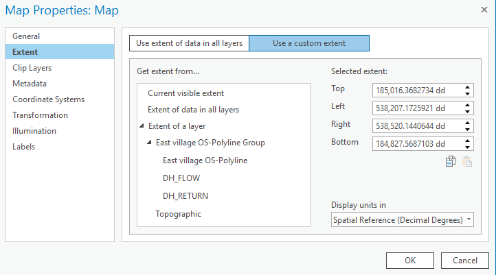
Thanks for your idea, I have tried it and found that it is working with DWG and DXF, so it looks I can import them into ArcGIS Pro, however, I think I cannot set the OSGB coordinate system properly in ArcGIS see the below picture for this:
 My question would be when you set the OSGB or any other coordinate system which is not WGS or UTM on your computer like the picture below:

Could you change the coordinates to OSGB at the bottom of the map view? Or is it always in WGS or UTM?

Many thanks for any help.
- Mark as New
- Bookmark
- Subscribe
- Mute
- Subscribe to RSS Feed
- Permalink
- Report Inappropriate Content
I downloaded your dwg and took a look. The dwg loads fine for me (Pro 2.3). The problem is the CAD file is not in OSGB36.
OSGB36 is a geographic coordinate system; so the coordinates are decimal degrees (geographic) coordinates. Those coordinates in the DWG are certainly not OSGB36 because they are clearly in a projected coordinate system, that is, in meters or feet, not degrees. To have things plot in the right place (since your dwg file has no coordinate system defined) you need to find out what the xy coordinates are, and set the map coordinate system to it. If the coordinate system you set for the map matches the cad file's xy values, the basemap will appear to line up under your CAD linework.
You may want to check this out again too, but you definitely are stuck until you find out what the XY coordinates in your DWG file are.
Map units, location units, and display units—ArcGIS Pro | ArcGIS Desktop
I hope this is helpful.
- Mark as New
- Bookmark
- Subscribe
- Mute
- Subscribe to RSS Feed
- Permalink
- Report Inappropriate Content
Hi Curtis,
Thank you for your help. You highlighted that I use the wrong kind of coordinate system. I chased the "British National Grid" in the Projection. I have found more information about it here What are map projections?—Help | ArcGIS for Desktop. Many thanks for your help again.
Here is the result:

- Mark as New
- Bookmark
- Subscribe
- Mute
- Subscribe to RSS Feed
- Permalink
- Report Inappropriate Content
Hi Curtis,
Sorry to ask you again. Do you know where can I set the coordinate system for the layers itself as it looks this is my new problem prior to the publishing?


- Mark as New
- Bookmark
- Subscribe
- Mute
- Subscribe to RSS Feed
- Permalink
- Report Inappropriate Content
I suggest copying the CAD features into a file geodatabase with the Feature Class to Feature Class tool and assign the BNG coordinate system to the gdb feature class with the Define Projection tool.
- Mark as New
- Bookmark
- Subscribe
- Mute
- Subscribe to RSS Feed
- Permalink
- Report Inappropriate Content
Hi Curtis,
Thank you it went quite quick as your description was good and useful. Thanks for that.
Sorry, just one more thing. I could make a map package and upload it into my ArcGIS account. Do you how can I make a map which can visible on the web and not just on ArcGIS Pro?

Many thanks again. I could achieve more today than in the all last week.