- Home
- :
- All Communities
- :
- Products
- :
- ModelBuilder
- :
- ModelBuilder Questions
- :
- Why are Modelbuilder "Bearing Distance To Line" re...
- Subscribe to RSS Feed
- Mark Topic as New
- Mark Topic as Read
- Float this Topic for Current User
- Bookmark
- Subscribe
- Mute
- Printer Friendly Page
Why are Modelbuilder "Bearing Distance To Line" results different from manually drawn direction/distance function
- Mark as New
- Bookmark
- Subscribe
- Mute
- Subscribe to RSS Feed
- Permalink
- Report Inappropriate Content
I created a model to plot a line for specified distances along a specified azimuth, then plot another line from the end vertice of that line for a specified distance in a perpendicular direction, then generate a point from end point of the second line. I used the “Bearing Distance To Line” tool to pull from a table that lists degree values to four decimal points (for example, 132.2458, 45.3789, etc.). The model seems to run fine, but the orientation of the automatically generated line is different from a manually generated line using the distance/direction function, even though the inputs are exactly the same. I thought maybe the projections were different for the two feature classes, but they are the same as well. I cannot figure out why this is happening or which result is more accurate, and was hoping someone might be able to help.
Solved! Go to Solution.
Accepted Solutions
- Mark as New
- Bookmark
- Subscribe
- Mute
- Subscribe to RSS Feed
- Permalink
- Report Inappropriate Content
Kathy and Dan, I did speak at length with ESRI technical support about this issue. I went through three different levels of support and at the end the tech support analyst said that both outputs were correct. The difference, according to tech support, is that the editor tool draws lines using "planar" geometry, while the bearing distance to line tool draws lines in a "geodesic" geometry. The tools cannot at this time draw lines in the same geometry, so they will appear different. Tech Support said they would submit a request to the programmers for an "enhancement" to address this problem, which would be incorporated in some future update to the program. I just downloaded ArcGIS Pro 2.2.3, and it doesn't appear that they have fixed the problem in that version yet. I personally think this is a fairly major discrepancy; maybe if you reach out to ESRI we can get some momentum on the issue?
- Mark as New
- Bookmark
- Subscribe
- Mute
- Subscribe to RSS Feed
- Permalink
- Report Inappropriate Content
When you say 'manual' are your referring to using the tool itself outside of your model?
Bearing Distance To Line—Data Management toolbox | ArcGIS Desktop (there is one for arcmap)
I wouldn't compare the model output to anything other than the tool output.
- Mark as New
- Bookmark
- Subscribe
- Mute
- Subscribe to RSS Feed
- Permalink
- Report Inappropriate Content
Thank you, Dan. Sorry that I wasn't more clear. When I said "manual" I meant using edit to create a new line feature, right-clicking as it is being drawn, selecting the direction/distance function, and then inputting the bearing in the "Horizontal/NAz" field, and the distance in the "Distance/ftUS" field. I left the "Pitch/dd" set at it's default value of 0.
- Mark as New
- Bookmark
- Subscribe
- Mute
- Subscribe to RSS Feed
- Permalink
- Report Inappropriate Content
pardon the pun... but that is a 'sketchy' method and I don't know if it has the same controls over it that creating a featureclass has. I would perform the comparison as I suggested first
- Mark as New
- Bookmark
- Subscribe
- Mute
- Subscribe to RSS Feed
- Permalink
- Report Inappropriate Content
I did follow your suggestion and used the "Bearing Distance to Line" from the data management toolbox, and that line drew the same as the one derived from the model. I'm still trying to figure out why the "sketch" method is different and which one is more accurate. I assume from your suggestion that you think the one from the data management toolbox is more accurate; my concern was whether it was rounding the azimuth value (which has four decimal points) before applying it, while the "sketchy" method was not. Thanks.
- Mark as New
- Bookmark
- Subscribe
- Mute
- Subscribe to RSS Feed
- Permalink
- Report Inappropriate Content
Robert... you would have to do the "maths" to see whether angle 132.2458 versus 132 would produce the deviation at your distance.
- Mark as New
- Bookmark
- Subscribe
- Mute
- Subscribe to RSS Feed
- Permalink
- Report Inappropriate Content
Dan, I'm not sure what you meant when you suggested doing the "maths." However, I dropped all decimals, then again ran the "bearing distance to line" tool and compared the results with a line created using the editor. I drew "L-shaped" lines using the same input for both tools: Line 1 was an azimuth of 312 degrees for a distance of 150 ft followed by an azimuth of 42 degrees for 50 feet; Line 2 was on an azimuth of 312 degrees for a distance of 200 ft followed by an azimuth of 42 degrees for 80 feet. I used the same coordinate system (NAD 1983 StatePlane Virginia North FIPS 4501 Feet) for both feature classes, but the results were again different (see attached graphic), with a difference of 3.14 feet on the longest line and 2.31 feet on the shorter line. I did not use any decimals, so it can't be a rounding error. This is very frustrating to me because I don't know why they wouldn't be the same, nor do I know which output to trust. 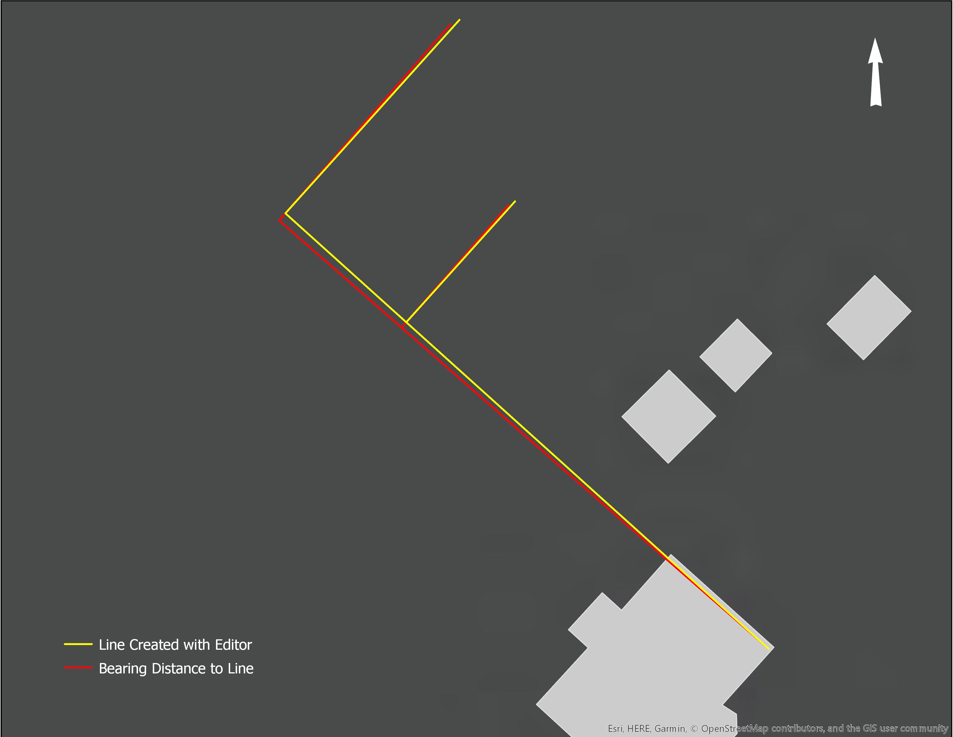
- Mark as New
- Bookmark
- Subscribe
- Mute
- Subscribe to RSS Feed
- Permalink
- Report Inappropriate Content
I would file a Tech Support issue since you should be able to use both methods.
If the dataframe and the output featureclasses are in the same coordinate systems, then you have ruled that out.
I would trust the tool but... who knows.
I am more concerned that the angles are slightly different from the same origin. If the angle specification was identical and the coordinates systems were identical, then they should be the same. The distance issue could be due to a datum difference or some other specification. Just ship it off for testing with your data would be your best bet.
- Mark as New
- Bookmark
- Subscribe
- Mute
- Subscribe to RSS Feed
- Permalink
- Report Inappropriate Content
Thank you, Dan. I used exactly the same parameters for each method and I agree that the angles appear to be more of a problem than the distances. I will give tech support a try.
- Mark as New
- Bookmark
- Subscribe
- Mute
- Subscribe to RSS Feed
- Permalink
- Report Inappropriate Content
Hi Robert,
I was searching and found your post regarding similar results I'm getting for drawing a line with the same bearing using the editor direction/distance compared to the Bearing Distance to Line tool. I'm really curious about the difference in angles between the lines. Did you get a response from tech support on this?
Thanks,
Kathy