Turn on suggestions
Auto-suggest helps you quickly narrow down your search results by suggesting possible matches as you type.
Cancel
- Home
- :
- All Communities
- :
- Products
- :
- Mapping
- :
- Mapping Questions
- :
- Re: Schematic Diagram Generation Using XML Builder
Options
- Subscribe to RSS Feed
- Mark Topic as New
- Mark Topic as Read
- Float this Topic for Current User
- Bookmark
- Subscribe
- Mute
- Printer Friendly Page
Schematic Diagram Generation Using XML Builder
Subscribe
1586
9
08-16-2012 05:31 AM
08-16-2012
05:31 AM
- Mark as New
- Bookmark
- Subscribe
- Mute
- Subscribe to RSS Feed
- Permalink
- Report Inappropriate Content
Hi,
We are currently working in a project to build a Schematic diagram using the XML data. I would like to understand the feasibility in generating the enclosed Schematic diagrams using the ESRI XML builder or by using the Schematics SOE provided in the 10.1 version.
Can anyhow help us in understadning the approach in meeting this kind of requirement.
Regards,
Srikanth.G
9 Replies
08-16-2012
08:36 AM
- Mark as New
- Bookmark
- Subscribe
- Mute
- Subscribe to RSS Feed
- Permalink
- Report Inappropriate Content
Hi Srikanth,
First of all, the xml capabilities and SOE capabilities are completely different concepts. There is desktop capability and there is server capability (SOE). In either case, there is an XML Builder that can be used to pass the desired data to schematics. The main reason to use an XML Builder would be that the data is not in a standard geometric network or network dataset, which those cases have specific Builders to deal with those networks. After you get the data to schematics (xml builder, standard builder, network dataset builder or Custom Query), then you have to deal with the physical layout (layout algorithm) on the screen. The core product only has generic layout algorithms and tools that would allow you to do this manually. If you want it automated, then you will also need to create a custom layout algorithm that does exactly what you need. Start on the desktop and get it working, then transition the builder and layout algo to the server.
So it is possible, but will likely require at least a custom layout.
I would suggest you spend some time watching the videos available on the resource center which explain the basics of schematics and go through the various builders.
Once you have a better handle on that, then look at the sample for creating a custom layout algorithm. There is also a sample for an xml builder. After all that, see what questions you still have.
Thanks,
Rick
08-19-2012
09:53 PM
- Mark as New
- Bookmark
- Subscribe
- Mute
- Subscribe to RSS Feed
- Permalink
- Report Inappropriate Content
Hi Rick,
Thank you very much for your reply.
Let me explain, what I am actually looking. May be I am failed to post the query properly. We have created schematics of a non geometric data using the XML builder with Smart tree layout and published in the browser using the ArcGIS Server. Now I would like to generate schematics for ISP details (port level) of the non geometric data, through XML builder only.
As you explained, will it be possible through the XML builder, if I customize the algorithm to generate these kinds of diagrams. I understand that, XML builder, supports only these 4 elements (Node Feature, Link Feature, NodeonLink/Sublink).How can I represent a polygon feature (box with all the ports inside) with these elements. If not, Will it be possible to meet this requirement using SOE objects and how.
Please let me know for any additional information required.
Thanks in advance.
Regards,
Srikanth.G
08-20-2012
11:46 AM
- Mark as New
- Bookmark
- Subscribe
- Mute
- Subscribe to RSS Feed
- Permalink
- Report Inappropriate Content
Hi Srikanth,
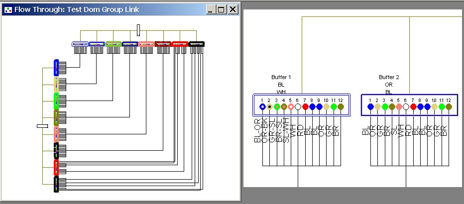
Schematics supports the 'container' concept. When you create the schematic feature class in configuration, set it as a Point type but with polyline geometry. So you have a node feature with an "ExternalUniqueID" that is going to end up drawing as a polyline geometry. Now any feature that goes inside it (node or link etc...), you just set its xml for "RelatedContainerID" = to the "ExternalUniqueID" of that node 'container' feature. The attached example of a telco splice point internal shows this concept. The Buffer Tubes are containers around the actual fiber nodes. You can also search the schematic help system for 'container' to find out more information.
Rick
08-22-2012
08:52 PM
- Mark as New
- Bookmark
- Subscribe
- Mute
- Subscribe to RSS Feed
- Permalink
- Report Inappropriate Content
Hi Rick,
Thanks for your support.
I hope this will definitely help me in addressing this requirement.
Regards,
Srikanth.G
Thanks for your support.
I hope this will definitely help me in addressing this requirement.
Regards,
Srikanth.G
09-21-2012
03:28 AM
- Mark as New
- Bookmark
- Subscribe
- Mute
- Subscribe to RSS Feed
- Permalink
- Report Inappropriate Content
Hi Rick,
Can you help me with a demo software or guidance to see a telco splice point like in the picture that you posted?
Thanks.
Radu.
Can you help me with a demo software or guidance to see a telco splice point like in the picture that you posted?
Thanks.
Radu.
09-21-2012
09:45 AM
- Mark as New
- Bookmark
- Subscribe
- Mute
- Subscribe to RSS Feed
- Permalink
- Report Inappropriate Content
That is a custom algorithm that is only exposed to customers via our partners (Telcordia (Eriksson) and Telvent (Schneider)) at the moment. We are just now deciding if this will be something we put into the core or provide on the side that will work with our Esri Telco data model. If you have an xml file (following our xsd) that describes one of your splice points, I might be able to run it through the algorithm and show you the results.
09-22-2012
11:26 AM
- Mark as New
- Bookmark
- Subscribe
- Mute
- Subscribe to RSS Feed
- Permalink
- Report Inappropriate Content
That is a custom algorithm that is only exposed to customers via our partners (Telcordia (Eriksson) and Telvent (Schneider)) at the moment. We are just now deciding if this will be something we put into the core or provide on the side that will work with our Esri Telco data model. If you have an xml file (following our xsd) that describes one of your splice points, I might be able to run it through the algorithm and show you the results.
Thank you Rick,
I don't have the file, i am looking for a solution to see a splice diagram in Arcgis.I know your partner's software, but are too expensive for the company i work for, so i'm trying to find a alternative. Do you know if is a workaround in the Telecom Template to use for seeing a splice diagram?
09-28-2012
02:08 PM
- Mark as New
- Bookmark
- Subscribe
- Mute
- Subscribe to RSS Feed
- Permalink
- Report Inappropriate Content
There isn't a work-around in the core template. However...we are looking at putting this splice point into the template sometime in the near future, but I just can't guarantee when or if it will happen at all. It will also end up being based off the xml builder. So there will be an external component that will understand how to get the 'internal' data and send it to schematics where the algorithm will be applied.
10-01-2012
12:26 AM
- Mark as New
- Bookmark
- Subscribe
- Mute
- Subscribe to RSS Feed
- Permalink
- Report Inappropriate Content
Thank you for your response.
Best regards,
Radu.
Best regards,
Radu.