- Home
- :
- All Communities
- :
- User Groups
- :
- Local Government Solutions Users
- :
- Questions
- :
- Parcel Drafter XY location and meters/feet issue
- Subscribe to RSS Feed
- Mark Topic as New
- Mark Topic as Read
- Float this Topic for Current User
- Bookmark
- Subscribe
- Mute
- Printer Friendly Page
Parcel Drafter XY location and meters/feet issue
- Mark as New
- Bookmark
- Subscribe
- Mute
- Subscribe to RSS Feed
- Permalink
- Report Inappropriate Content
I recently started using Parcel Drafter in the standard WAB and came across some weird issues from my initial setup.
1) The XY location does not seem to work (or I do not know how to work it). Whenever I put anything in, it sends me to 'null island'. Whenever I use the testing application that Esri hosts, it still does not take me where I want it to go. I assumed that X was Longitude and Y is Latitude. Is it Northing and Easting instead? Is there documentation on setting the XY location?
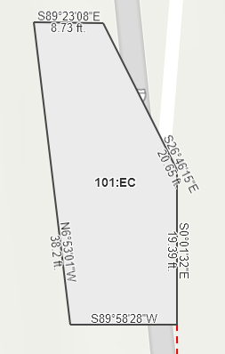
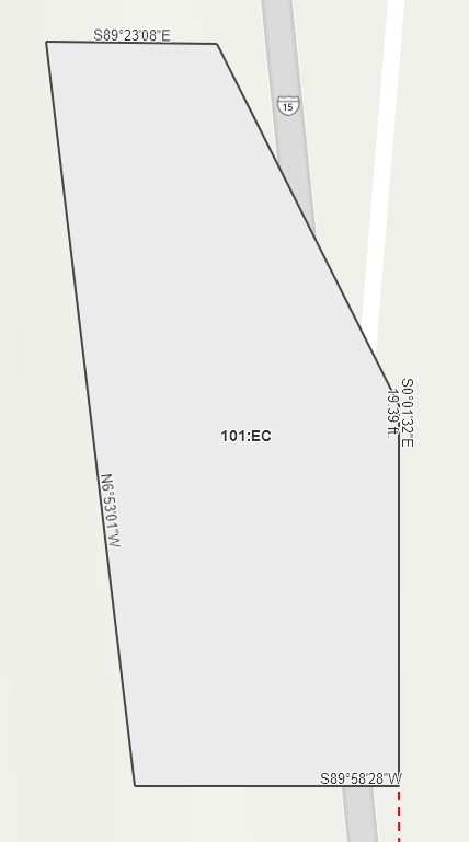
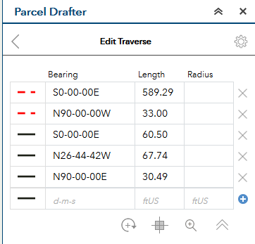
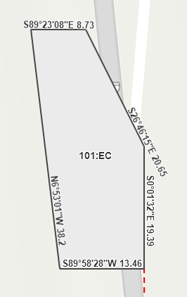
2) I put in a simple land unit and it worked as expected with five simple calls. However, it converted my inputted ftUS into what seems to be meters, but still labels it as feet. I am not sure where this conversion is happening and/or how to stop it. This does not happen in the testing application. Here is a screenshot:
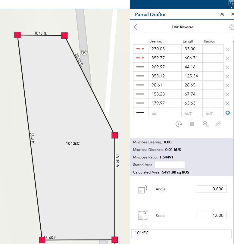
You can see where it is labeled as 38.2 ft. on the left hand side. But the written call on the right hand side says 125.34 feet (and that's in "ftUS"). Where and why is this conversion happening?
3) Bonus question, when I put in a bearing like "s89-23-08e" it auto-converts to 90.61, which makes sense. Is there a way to keep my original input of the dms with directions?
4) Additional and harder bonus question: Is there a way to input in a ton of calls (of metes and bounds) at once with a CSV or spreadsheet to draw a massive parcel (or to draw many parcels)?
Thanks for your help!
tagging Chris Buscaglia
- Mark as New
- Bookmark
- Subscribe
- Mute
- Subscribe to RSS Feed
- Permalink
- Report Inappropriate Content
Hi Adrian,
1. Please send me the coords. that you are attempting to enter (or one better - the document that references that coord.)
2. Is the coordinate systems units that you are using in meters? If so, we'll have to update the label expression to convert to feet. We recommend that your edit layer be in the coordinate system of your choice - did you set the coordinate system before you deployed the app.?
3. The conversion from quadrant bearing to decimal degrees is happening because of the settings in the widget - click the sprocket in the upper right hand corner to change the Direction or Angle Type to 'Quadrant Bearing' and the Direction or Angle Units to 'Degrees, Minutes, Seconds'.
4. Currently no, but we can look into the requirement. Out of curiosity, how was the CSV or Excel doc. generated?
- Mark as New
- Bookmark
- Subscribe
- Mute
- Subscribe to RSS Feed
- Permalink
- Report Inappropriate Content
Chris,
Thanks for the reply. I put in somewhat arbitrary coordinates but did not have success.
1. Lat: 41.535496
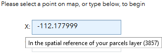
Long: -112.177999
2. I just used the default setup that was created for me in ArcGIS Online when I ran through the ArcGIS Solutions task in ArcGIS Pro > Deploy and ArcGIS Solution > Local Government > Parcel Drafter > Deploy.
I just the default map that was created in Pro which was in WGS84 Web Mercator (that has a units of Meters). Was this my issues? Should I deploy the solution from a map that has a coordinate system in Feet? Either way, it's hosted in AGOL and there is only one coordinate system in there so I don't have control over that.
(when I hover over the XY values, it says "In the spatial reference of your parcels layer (3857)"):
3. While I like how changing those parameters changes how my WAB widget looks, It still shows numbers in the actual web map. Is there a way for the bearing text to retain the d-m-s values?
vs
4. That's a good question and I'll have to get back with you on that. This was a request from my boss who uses something called Deed Plotter to plot deeds from CAD drawings. I think this software, or some software, can generate a bunch of text for all the calls of a parcel with related info (like name, type, etc.).
- Mark as New
- Bookmark
- Subscribe
- Mute
- Subscribe to RSS Feed
- Permalink
- Report Inappropriate Content
Adrian,
The sample application that we maintain uses State Plane coordinates and units, to make that work - you need to enter coords. if feet.
For your application, the coords. need to be entered in meters. For example, enter something like X = -9,818,344 Y = 5,122,119. You can also use the coordinate widget to locate a start point and set the units to meters to test it out. We did this so that you can enter (for example State Plane Coords.) in whatever units your coord. system is in without converting to Lat/Long. Many states require coords. in state plane for platted subs.
To change your application to use another coord. system, you can do that before you deploy - the parcel drafter layers will be set to that coordinate system, the basemap will remain in web mercator for this particular solution.
Deployment options - ArcGIS Solutions Deployment Tool | ArcGIS Solutions
The data for angles is stored in the feature layer as doubles, so the Parcel Drafter can't add strings to that field. I can look into a enhancement to also store string values in another field. What exactly would you like to do with that data? Knowing that may help me give you some guidance for a workaround/workflow that may satisfy the requirement.
Chris
- Mark as New
- Bookmark
- Subscribe
- Mute
- Subscribe to RSS Feed
- Permalink
- Report Inappropriate Content
Chris,
This is Jefferson, Adrians boss. Thank you for being so responsive to us. We like what you have built and were trying to test its possibilities and limitations to see if we could get it working well for our use case. We would love to use this tool for our needs of data entry to aid in the generation of closure reports. Adrian and I both think we have a bead on the first two points he brought up. Thank you.
The big reason we wanted the angle field to possibly store the textual bearing string rather than just azimuth is so we could get it to display in the labels of the parcel/traverse. We can get the angle to show up, however it only shows in the azimuth form. If we could change the label display that would also solve the issue. Storing the textual bearing in a separate field would work well for us as well.
The fourth point Adrian brought up is important, but secondary in my mind to a few other problems.
The first would be data entry for curves. Your method is limited to the following:
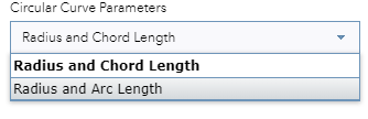
Radius and Chord Length actually requires Chord Bearing, Radius, and Chord Length, Radius and Arc Length actually requires Chord Bearing, Radius, and Curve Length. The options labels are a bit misleading in this regard.
Curves in documents are more diverse than these options. Much more, actually. A tool like this would be useful when diversity in data entry was available. Here is a screen shot of software we use now (that we would like to abandon) showing the different types of curve information that show up in legal documents.
Generally any three elements of a curve can accurately draw the curve. They would still generally work within the fields you have created.
Are you familiar with these possible definitions.
- Mark as New
- Bookmark
- Subscribe
- Mute
- Subscribe to RSS Feed
- Permalink
- Report Inappropriate Content
Hi Jefferson,
The feedback your team has given has been great, and we probably need to add some additional documentation in a couple areas.
For some reason, the screenshot from (deed plotter?) didn't come through, but maybe the following helps out?
To enter a chord bearing - please enter the chord bearing into the bearing field in the grid. To enter tangent curves, type *tb in the Bearing text box, or * to make the next line the same bearing as the previous.
Also, I'm working on a label expression for you that will display the bearings as you suggest, I'll keep you posted.
Chris
- Mark as New
- Bookmark
- Subscribe
- Mute
- Subscribe to RSS Feed
- Permalink
- Report Inappropriate Content
Please try this to complete the Bearing/Distance issue that you were having.
Modify the custom label expression for the lines label in the webmap to have the following code.
CBuscaglia-esristaff wrote:
Hi Jefferson,
The feedback your team has given has been great, and we probably need to add some additional documentation in a couple areas.
For some reason, the screenshot from (deed plotter?) didn't come through, but maybe the following helps out?
To enter a chord bearing - please enter the chord bearing into the bearing field in the grid. To enter tangent curves, type *tb in the Bearing text box, or * to make the next line the same bearing as the previous.
Also, I'm working on a label expression for you that will display the bearings as you suggest, I'll keep you posted.
Chris

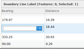
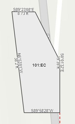
This will make the label appear like this, even better...you can add the same code to the popup for the lines and it will appear in the table for the lines layer (like a new field).
- Mark as New
- Bookmark
- Subscribe
- Mute
- Subscribe to RSS Feed
- Permalink
- Report Inappropriate Content
Chris,
Thanks for posting this. However, I am not sure it copied and pasted correctly into the thread. When I put it into the label expression, it showed up as one line, no breaks. I noticed that a few things were grayed out because there were no breaks, like this snippet:
var QuadrantBearingFormat = true; //set as 'true' for quadrant bearing and false for north azimuth var direction=$feature.Bearing;
Would it be possible for you to copy and paste that label expression into a text editor (like notepad++) and then copy and paste it back into this thread? I tried going through and adding my own breaks but I keep getting an error for Unexpected Identifier.
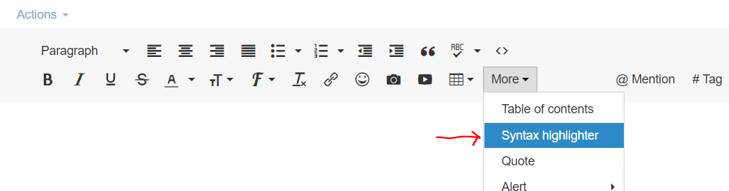
I find that it helps to use the syntax highlighter for displaying code in geonet:
Thanks,
Adrian
- Mark as New
- Bookmark
- Subscribe
- Mute
- Subscribe to RSS Feed
- Permalink
- Report Inappropriate Content
var QuadrantBearingFormat = true; //set as 'true' for quadrant bearing and false for north azimuth
var direction=$feature.Bearing;
var distance=$feature.Distance;
var radius=$feature.Radius;
var arclength=$feature.Arclength;
var radius2=$feature.Radius
var prefix;
var postfix;
var bearing;
var quadbearing;
var validValuesArray;
var missingValuesArray;
var degrees;
var minutes;
var seconds;
var DMS;
function NorthAzimuth2Quadbearing(azimuth){
if (azimuth<90 && azimuth>=0){
bearing=azimuth;
prefix = "N";
postfix= "E";}
else if (azimuth<180 && azimuth>=90){
bearing=180-azimuth;
prefix = "S";
postfix= "E";}
else if (azimuth<270 && azimuth>=180){
bearing=abs(180-azimuth);
prefix = "S";
postfix= "W";}
else if (azimuth<360 && azimuth>=270){
bearing=360-azimuth;
prefix = "N";
postfix= "W";}
degrees=floor(bearing);
minutes=floor((bearing-degrees)*60)
seconds=((bearing-degrees-minutes/60)*3600)
if (seconds>=59.5){
seconds=0;
minutes+=1;
if (minutes==60){
minutes=0;
degrees+=1;}}
quadbearing=prefix+degrees+"°"+text(minutes,"00")+"'"+text(seconds,"00")+"''"+postfix;
return quadbearing;
}
function DMS(bearing){
degrees=floor(bearing);
minutes=floor((bearing-degrees)*60)
seconds=((bearing-degrees-minutes/60)*3600)
if (seconds>=59.5){
seconds=0;
minutes+=1;
if (minutes==60){
minutes=0;
degrees+=1;}}
DMS=prefix+degrees+"°"+text(minutes,"00")+"'"+text(seconds,"00")+"''"+postfix;
return DMS;
}
if (IsEmpty(direction)==false) { //if direction exists
if (IsEmpty(radius)==true) { // if radius is not populated --> it is a straight line
if (QuadrantBearingFormat==true) { //using quadrant bearing format
return NorthAzimuth2Quadbearing(direction) +' '+ text(round(distance,2));
}
else { //using north azimuth format
return DMS(direction) + ' ' + text(round(distance,2));
}
}
else { //radius is populated --> it is a curve
if (radius>0) { // if radius is positive --> right
return "R=" + text(radius) + text(arclength);
}
else { // if radius is negative --> left
return "R=" + text(abs(radius)) + text(arclength);
}
}
}Try this - looks like Arcade isn't an option in the dropdown 
Adrian Welsh I simplified the code a bit (Above)
- Mark as New
- Bookmark
- Subscribe
- Mute
- Subscribe to RSS Feed
- Permalink
- Report Inappropriate Content
Chris,
That worked great! Maybe Arcade should be added to the dropdown list (or it looks so similar to javascript, maybe that is the better option).
So, I tried taking it one step further to show angle on top of the line and distance on the bottom of the line, but AGOL does not really treat labels very well....
Any time I pan and zoom, it randomly decides which labels it is going to show off: