- Home
- :
- All Communities
- :
- Products
- :
- Geoprocessing
- :
- Geoprocessing Questions
- :
- How to buffer a polyline without overlap at vertic...
- Subscribe to RSS Feed
- Mark Topic as New
- Mark Topic as Read
- Float this Topic for Current User
- Bookmark
- Subscribe
- Mute
- Printer Friendly Page
How to buffer a polyline without overlap at verticies
- Mark as New
- Bookmark
- Subscribe
- Mute
- Subscribe to RSS Feed
- Permalink
- Report Inappropriate Content
[ATTACH=CONFIG]32063[/ATTACH]
- Mark as New
- Bookmark
- Subscribe
- Mute
- Subscribe to RSS Feed
- Permalink
- Report Inappropriate Content
Jim,
I'm just curious if you've found an automated solution to this, as I've recently posted the same question.
If you haven't, it's possible to do it manually through a series of steps using 'copy parallel' rather than buffer and creating polygons from lines.
As for an automated process, I haven't discovered one yet.
- Mark as New
- Bookmark
- Subscribe
- Mute
- Subscribe to RSS Feed
- Permalink
- Report Inappropriate Content
Here is the majority of the solution using a geoprocessing approach without scripting. It requires an Advanced license to use all of the tools listed here. A script may be able to bypass the need for so many tools, but the basic steps to get from a set of lines to a divided buffer should more or less follow this process.
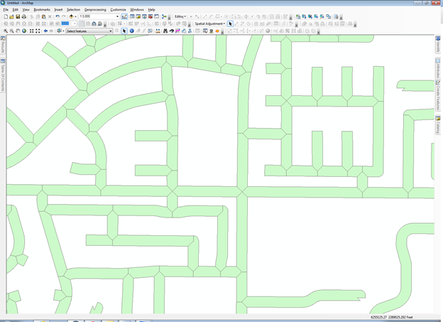
I do know that the first step is to get a buffer shape that will form the overall outline to be segmented. That shape will dissolve all lines together without any attributes dividing the segments. I would use Flat ends. See the resulting exterior boundary of the buffer shown in the picture at the bottom (interior lines are created in the rest of this process):
It is that buffer which must be divided at the joints and the resulting divided set of polygons must be attributed by the original divided lines.
Next I need the intersection point at every line junction where the attributes change and there are separate lines. Preferably unnecessary pseudo nodes have been eliminated. I would use the Intersect tool with the POINT option on the segmented lines to extract those points. This does not create a box at 4 way intersections, it creates an X, which is the only way to have polygons that only cover one line. A box would have to be created a different way and a manual choice would have to be made to assign only one line's attribute set.
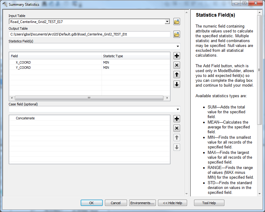
Next I added two double fields for the X and Y coordinates of the intersection points and a text field with a concatenation of the points. Then I do a Summary Statistics with the XY concatenation as the unique case value and the MIN_X and MIN Y coordinate summary to get an XY Event table of the points. Make that table into an XY Event layer.
Create a fairly small buffer around these XY Event Layer intersection points. I used 20 feet and kept the X_Y_LINK, FREQUENCY, X_COORD and Y_COORD fields.
Then I used the Features to Lines tool to convert the outer circular buffer boundaries around the intersections to lines as a SHAPEFILE You cannot output to a file geodatabase because it will use true curve arcs which won't work for the steps that follow.. Dissolve these arcs keeping the X_Y_LINK, FREQUENCY, X_COORD and Y_COORD fields to rejoin overlapping buffer outlines that are split up by the Features to Lines tool back to their circular shape.
Next extract the end point of the circular lines to find the position where the circle will split that does not touch the original lines using the Feature Vertices to Point tool with the START option.
Now I can intersect these circular lines with the original lines and use the POINTS option to get all positions on the circle cut by the original lines.
I can then use the Split Line at Points tool on the circular lines with these latest points where the circle is cut by the intersecting original lines. I used a search tolerance of about .01
Now select all of the points that were at the start of the circle. Do a Search by Location to Remove from the Current Selection all points that are within about 1 foot of the points that cut up the circle. This may miss some very small arcs where a line and the circle start are close together, which may need to be cleaned up manually after the next step.
The remaining circle ends should select the cut up lines on the circle outline to find the pair that should merge together that are not intersected by an original line. Dissolve these lines keeping the X_Y_LINK, FREQUENCY, X_COORD and Y_COORD fields and use the Unsplit lines option to create a new feature class. You may delete these arcs from the cut up circle outlines. Now clean up any small arcs where the start of the circle was close, but not on an original line manually.
For the remaining arcs that were not touched by a circle starting point use the Feature Vertices to Points tool with the MID option on the remaining circle portions. Do the same with the Dissolved circle portions and append the two point feature classes together. This will only work correctly if the circular arcs are in a shapefile and not a file geodatabase.
Add an X_TO and a Y_TO double field to these latest bearing points and calculate the coordinates of these new points into them.
Use the XY To Line tool to make the X_COORD and Y_COORD the start of the line and the X_TO and Y_TO the end of the line.
Convert the original buffers of the dissolved lines to lines using the Features to Line Tool.
Copy these buffer outline into the Bearing lines feature class. Save the edit.
Now use the Extend tool and extend double or triple the distance of the original buffer and use the Extend to Extensions rule. Examine the result for anomalies involving arcs that are greater than 180 degrees or intersection points within the buffer of each other.
Use the Features to Polygons to convert the extended lines to polygons. Use the bearing lines to select polygons that actually enclose lines, the reverse the selection and delete the polygons from the buffer holes.
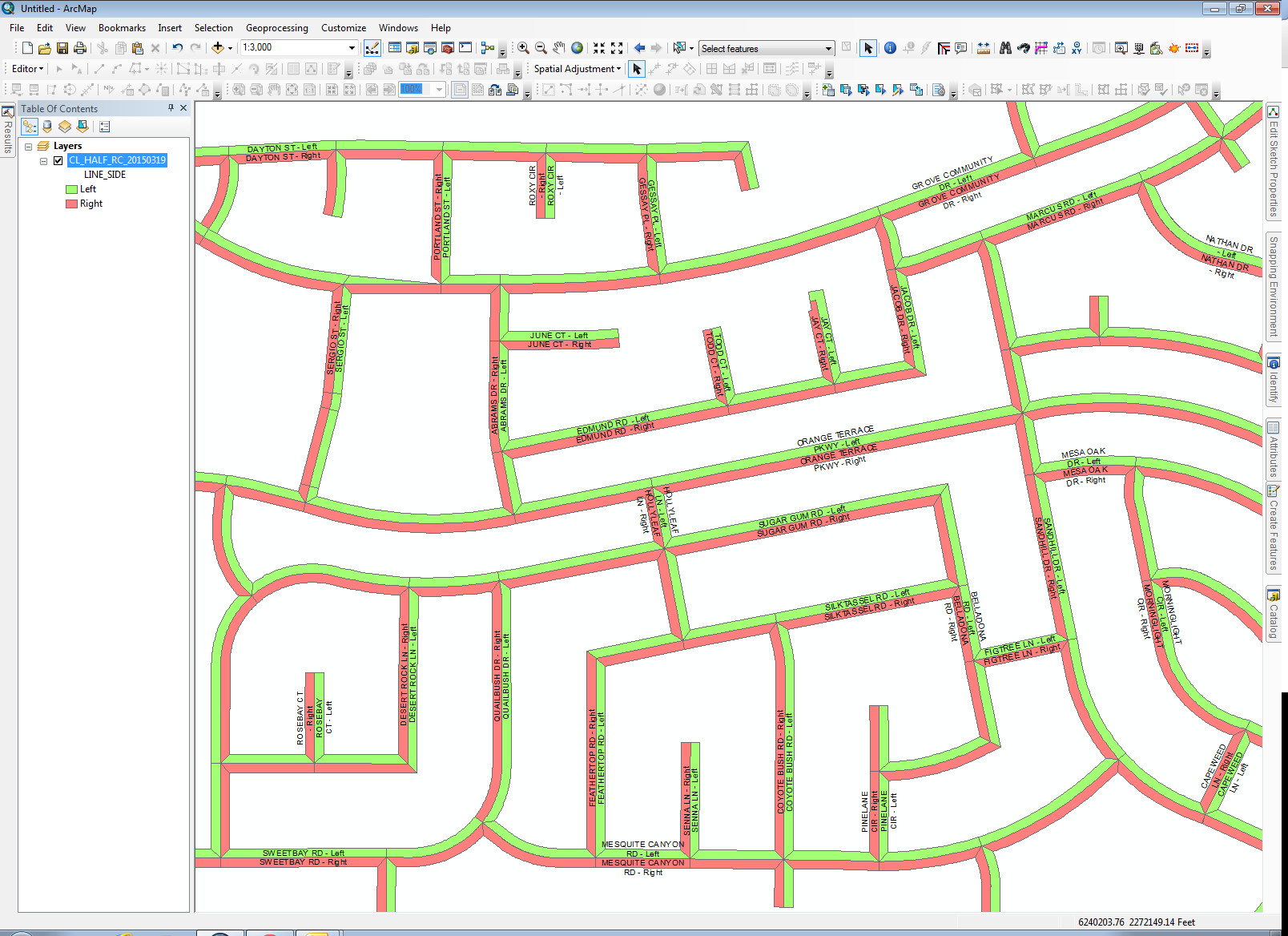
Use the Spatial Join tool to transfer the attributes of the original lines to the points that divided the intersection circles. .Use these points to Spatial Join attributes to the polygons. The end result looks like the picture below:
If certain roads were supposed to take away the triangular areas and you wanted a box intersection, a separate process would have to be developed by only buffering those roads with their attributes and cutting the intersection again and reassigning the triangular pieces to that line segment. The circle would only divide on those lines to form the bearing cut angles that would divide the box. However, without a way to classify the road that takes priority at the intersection, I cannot think of a way to get the box effect easily Wither way attributes would not divide the buffer on a through road at the intersections., but the lines segment end points would divide the circle and create the cuts at the center of the intersection genearly in line with the cross street.
- Mark as New
- Bookmark
- Subscribe
- Mute
- Subscribe to RSS Feed
- Permalink
- Report Inappropriate Content
Hi Richard,
Can you explain to me how you would create X_Y_LINK, FREQUENCY, X_COORD and Y_COORD fields?
So I have road polygons that I need to split at the intersection very similar to what you have done in the image. I have created center-lines based on the polygons and now I am just trying to cut the polygons. You help will be greatly appreciated.
Thanks
- Mark as New
- Bookmark
- Subscribe
- Mute
- Subscribe to RSS Feed
- Permalink
- Report Inappropriate Content
The Frequency field get created by the geoprocessing tools at some stage in the process (probably during a Dissolve for the buffer). The X_COORD and Y_COORD fields are double fields that you can calculate for the points using the geometry calculator or the field Python calculations !Shape.Centroid.X! and !Shape.Centroid.Y!. The X_Y_LINK concatenation can be as simple as doing the python calculation: Round(X_COORD, 😎 + ";" + Round(Y_COORD, 8). You should round to some level of precision acceptable to you, since you don't want extremely minor variations in the coordinate values to be interpreted as different points. I do a more sophisticated calculation to make sure all X and Y coordinates are always 12 characters long with a fixed decimal position that maintains 4 digits after the decimal, but for this exercise that is not necessary.
If your polygons are buffers of the Centerlines, rather than centerlines created to match preexisting polygons, then I am actually in the process of creating an Add-In tool that creates buffers like this much more easily and faster. It also populates the buffer polygons with the ObjectID of the source lines and optionally their attributes and splits the buffers on the left and right sides of the centerline (which is easy to merge into a single polygon per centerline using the centerline ObjectID field). It also creates sharp corners at knuckles, not rounded corners. See the attached picture. Unfortunately, it is not yet ready for general release, since the user interface has not been created. Let me know if you are interested in that tool.
- Mark as New
- Bookmark
- Subscribe
- Mute
- Subscribe to RSS Feed
- Permalink
- Report Inappropriate Content
Hi Richard,
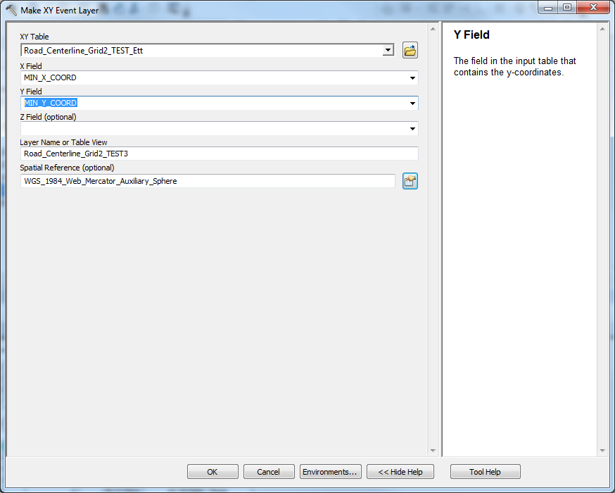
Thank you for replying so quickly. I have followed your steps and when I use Make XY Event Layer, the output is not where it should be.
I created my Intersects points based on the centerline that I created. Then I created the X_COORD and Y_COORD in Decimal Degrees and then Concatenated using, round( !X_COORD! , 😎 + ";" + ound( !Y_COORD! , 8). Then did a Summarize choosing X_COORD and Y_COORD Minimum. Then I created Make XY Event Layer.
I am very much interested in the tool. Do you have a tool for the previous instructions?
Thank You
- Mark as New
- Bookmark
- Subscribe
- Mute
- Subscribe to RSS Feed
- Permalink
- Report Inappropriate Content
No, I did not automate the instructions in this post. It was one of my earliest attempts to deal with this issue and I was working it out as I wrote it.
As far as the summary, did you use the concatenated coordinate value you calculated [round( !X_COORD! , 😎 + ";" + round( !Y_COORD! , 8)] as the case field? Your output should include every concatenated coordinate value in your table and the minimum X_COORD and Y_COORD associated with each concatenated value. Then you are sure you used the same spatial reference when you set up the XY Event table?
- Mark as New
- Bookmark
- Subscribe
- Mute
- Subscribe to RSS Feed
- Permalink
- Report Inappropriate Content
Yes that is what I did and when making XY, I choose the correct Spatial Reference
I am not sure why it is not projecting to the correct place, could it be the Min_X_COORD and Min__Y_COORD?
- Mark as New
- Bookmark
- Subscribe
- Mute
- Subscribe to RSS Feed
- Permalink
- Report Inappropriate Content
Is it projecting close to what is right or is it way off? Usually if it way off the X and Y coordinates got reversed somehow. Also, could you screen shot the table output records from the Summarize step. The numeric values in the Concatenate field and the values of Min X and Min Y coordinate fields should be basically match up. You could also try the Max X and Max Y in addition to the Min and compare the values. I am not sure how many digits are significant with this projection, so perhaps if there is variation between the Min and Max that would account for the variance in the location and you would need to round the concatenation to keep more significant digits to not blend distinct points together.
I also click on a known coordinate in the points layer to look at its snapped on-screen coordinates in the lower right corner of ArcMap and its calculated coordinates. If they are different by a significant amount (determined by moving the mouse to see how much the numbers change when the mouse moves) then you would need to find out what happened. They should be virtually the same.
- Mark as New
- Bookmark
- Subscribe
- Mute
- Subscribe to RSS Feed
- Permalink
- Report Inappropriate Content
Hi Richard,
I am highly interested in the Add-In tool you mentioned. Could you share it? My email address is healer02@gmail.com. I would appreciate so much.