- Home
- :
- All Communities
- :
- Products
- :
- Geoprocessing
- :
- Geoprocessing Questions
- :
- Re: Calculating building external wall from shapef...
- Subscribe to RSS Feed
- Mark Topic as New
- Mark Topic as Read
- Float this Topic for Current User
- Bookmark
- Subscribe
- Mute
- Printer Friendly Page
Calculating building external wall from shapefile
- Mark as New
- Bookmark
- Subscribe
- Mute
- Subscribe to RSS Feed
- Permalink
Hi GIS-people 😉
I'm a master student and new on this forum. I appreciate any help of yours.
I have two data set (attached):
- Shapefile of buildings containing the height of each building as well.
- A parcel shape file. Several buildings are assigned to a single parcel.
I am interested in calculating the sum of the surface of external walls of buildings (m2) in each parcel. In other words, I want to know how square meters (m2) of external walls I have in each parcel. However, it is important for me to exclude those walls which are in common in between of buildings. For instance, if two buildings with the heights of 10 m and 6 m are attached from one side, the goal would be to include 4 m of the 10 m external wall and exclude the 6 m which both walls are attached with each other.
I hope I was successful in describing the question. Thanks for your responses in advance.
Cheers,
Sara
Solved! Go to Solution.
- Mark as New
- Bookmark
- Subscribe
- Mute
- Subscribe to RSS Feed
- Permalink
You Rock Dude!
Thank you very much 
- Mark as New
- Bookmark
- Subscribe
- Mute
- Subscribe to RSS Feed
- Permalink
Sara, could you mark Xander's response Correct so that others know that the issue is resolved.
- Mark as New
- Bookmark
- Subscribe
- Mute
- Subscribe to RSS Feed
- Permalink
You are welcome. Good luck with the process.
- Mark as New
- Bookmark
- Subscribe
- Mute
- Subscribe to RSS Feed
- Permalink
Dear Xander
I am still working on the process you proposed... The flow is great,
however, I just got a bit of lost on the way with joining tables which
changes the ID's and FID's every time... I appreciate your tips on the
following. I thought of simplifying the process by replacing the parcel
with blocks. Blocks are aggregated parcels, without those annoying lines in
between! Attached is the file and you'll see what I mean (
https://www.dropbox.com/s/zmtvxdfyqdqz57l/block.zip?dl=0). So everything
stays the same, just instead of calculating the external walls of the
buildings in each parcel, this time I would like to calculate them in each
block. BTW with this process the surface of the walls are not counted,
right?
I appreciate your time in advance.
Cheers
- Mark as New
- Bookmark
- Subscribe
- Mute
- Subscribe to RSS Feed
- Permalink
Sure, you can replace the parcels by the building blocks, but you will be introducing some errors with some situations where a building is not located in any building block, like:


and
The advantage is that building blocks are not connected to each other and buildings will not share a wall to two blocks. Basically you can go either way depending on the level of detail your analysis need.
- Mark as New
- Bookmark
- Subscribe
- Mute
- Subscribe to RSS Feed
- Permalink
so by using blocks I dont need to proceed with the left_parcel and
right_parcel as the last step of what you have mentioned on your previous
posts, correct? In other words no need to worry about "single wall",
"inside single parcel", "a wall on the limit of two parcels"...(?) Which
means that I should perform a spatial from building_height_points with the
blocks and summarizing all the walls of each block. Would that be correct?
- Mark as New
- Bookmark
- Subscribe
- Mute
- Subscribe to RSS Feed
- Permalink
What I meant to say was that by using blocks the step to assign a wall to a block is less complex than using the parcels. However, you will still need to use the LEFT and RIGHT information to determine the height difference and the surface of the exposed wall.
- Mark as New
- Bookmark
- Subscribe
- Mute
- Subscribe to RSS Feed
- Permalink
Since you mentioned that the OBJECTID's and all the joining can be confusing, I wanted to simplify this by switching off the ID's and OBJECTID fields that aren´t the object id and use the original shapefiles. So we have building heights:

and parcels:

Both have a field named FID which is the object id.
When generating the lines of the building polygons the resulting attribute table looks like this:

Fields LEFT_FID and RIGHT_FID correspond to the field FID in the Building Heights shapefile and indicate which polygons are located on the left and right side.
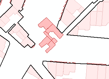
However, when I looked a little closer at the building height shapefile, I notice that many buildings consist of multiple polygons with different heights:

I will check how this affects the process and get back to you later today...
- Mark as New
- Bookmark
- Subscribe
- Mute
- Subscribe to RSS Feed
- Permalink
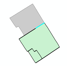
OK, it seems there is a problem when using the the overlapping polygons. I thought there would be, since for instance this line (in cyan):
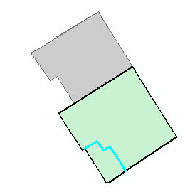
... is created twice. However this is what happens in the attribute table:
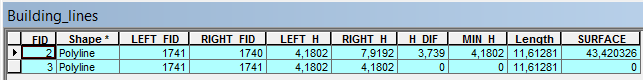
The LEFT_FID and RIGHT_FID will be the same, joining the same building height for left and right and the height difference "H_DIF" will be 0, so the surface will be 0.
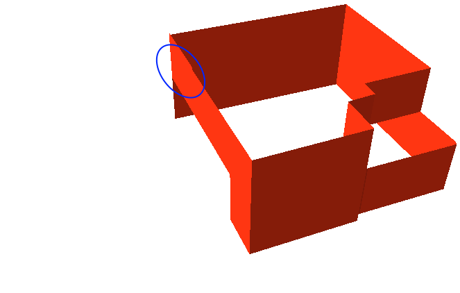
In 3D the situation looks as follows (using the building polygons and extruding on the field HEIGHT):
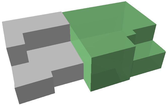
In case we are interested in the surface of the walls of the green building we can define the minimum height (left or right) of the neighboring buildings as base height and use the height difference as extrusion:

This looks almost OK, but there is a part of the wall that should not have been included:
If you look at it in 2D you will see that it created 4 lines from the neighboring polygons (see cyan line):
Looking at the attributes of selected lines:
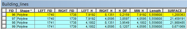
It learns us that it should ignore 3 of the 4 records and only include the one with the highest HEIGHTs. When there are two polygons with overlap composing a single building, the polygon with the highest HEIGHT should not start on the ground, but on the HEIGHT of the lowest polygon. Although this will complicate the analysis, it is possible to derive the surface of the exposed walls.
- « Previous
-
- 1
- 2
- Next »
- « Previous
-
- 1
- 2
- Next »