- Home
- :
- All Communities
- :
- Products
- :
- Data Management
- :
- Data Management Questions
- :
- CAD to GIS
- Subscribe to RSS Feed
- Mark Topic as New
- Mark Topic as Read
- Float this Topic for Current User
- Bookmark
- Subscribe
- Mute
- Printer Friendly Page
- Mark as New
- Bookmark
- Subscribe
- Mute
- Subscribe to RSS Feed
- Permalink
I am importing CAD files (stores plans) dwf/dwg into our ArcGIS system. Everything seems fine on that front except that I would like it to come in at the actual size of the store. In AutoCAD we do not have any geo referencing to the file however I would think with it being drawn to scale that I should at least be able to bring it in at that same scale just not the right place in the world. When I bring these files in they come in much larger than scale. Any trick or tips on how to do that. I would rather not do any manual adjusting.
Thanks,
Michael
Solved! Go to Solution.
- Mark as New
- Bookmark
- Subscribe
- Mute
- Subscribe to RSS Feed
- Permalink
Watch this at the 2:30 min mark Overlaying CAD data. Step three: Georeferencing CAD datasets | ArcGIS Video
This will show you how to scale it down
- Mark as New
- Bookmark
- Subscribe
- Mute
- Subscribe to RSS Feed
- Permalink
The video is cool to where you could do the scaling in ESRI, once you figure out the percent to scale. Although, If you can set these DWGs properly, should eliminate scaling, just need rotating. If you can, verify with text dimensions someone may have labeled in the CAD DWG - the 418 you refer to, could be inches (I know, most buildings are bigger than that) – no units are defined. There are some variables in process for this, like if you can't manipulate the originals then this is where I was suggesting to setup a new blank drawing for each. If your drawings are unitless like the your screenshot shows, go ahead and start a new blank drawing, use command ADESETCRDSYS and set the coordinate system to what you are using in GIS – if you can change the original DWGs, and if all of your drawings have no CS set and no units set, you can actually use this prompt, bottom section of the form, to set coordinate system for all of the drawings, all at once, but I have found the units have to be set as well working DWG to DWG – maybe you can try leaving unitless while having the CS set and bring in to ESRI environment may not care about the units and only look to the CS setting in the dwg?? Going back to the blank drawing setup, if you go that route, after setting a CS, set the units to match the CS units. Then bring in one of your drawings – best way is through task pane/map explorer, but this would depend on version of AutoCAD/Suite – sure way for all versions: xref command, right click attach dwg, once the drawing shows in this list, right click on it and use “Bind”. Save this drawing and now ESRI should find the settings for this drawing and convert/project the DWG units as it brings them in to display. You’ve got inches, feet, and meters that these software have to deal with. You should get the proper results, without manual scaling, if you can confirm your lengths in the DWGs and ensure they have the proper CS and units set. Only other issue might be if you are working GIS in older CS that may require 2 transformations – the CS warnings ESRI will give you cannot be ignored, should be well understood what is needed for proper transformations.
- Mark as New
- Bookmark
- Subscribe
- Mute
- Subscribe to RSS Feed
- Permalink
16493/3.28084(feet in a meter) then divided by 12 (inches) = 418.92218
- Mark as New
- Bookmark
- Subscribe
- Mute
- Subscribe to RSS Feed
- Permalink
So What I do is bring in the cad data
Position it where I want it with the georeferencing toolbar
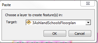
Then I have a layer already created for it, I ctrl + c and then ctrl + v to paste it to that layer.
Then you can publish it.
- Mark as New
- Bookmark
- Subscribe
- Mute
- Subscribe to RSS Feed
- Permalink
Thanks to both of your for your help. I have a lot more control over the GIS side of things and understand it better so I'm going to try and head down Rickey's path.
I like where we are heading. The problem is that once I have my layer where I want it I still have the errors from above. I tried adding a new group layer and moving the files over to that and then publish to server it still doesn't like something.
How do you handle this? I know you tried to explain it but I'm not understanding it.
- Mark as New
- Bookmark
- Subscribe
- Mute
- Subscribe to RSS Feed
- Permalink
Michael,
Are you copying each layer in the CAD group to a separate feature class?
After you do, you should not get so many errors when trying to publish.
- Mark as New
- Bookmark
- Subscribe
- Mute
- Subscribe to RSS Feed
- Permalink
Sorry to sound so stupid but can you walk me through how I would do this? Do you mean for me to export each (Point, Polyline, Annotation, Polygon, MultiPatch ) of these to shapefiles?
- Mark as New
- Bookmark
- Subscribe
- Mute
- Subscribe to RSS Feed
- Permalink
When I import cad I only use the annotation and line (you may need a polygon feature class)
I have two layers set up: the building_labels for the annotation (i have to import manually)
and they AshlandSchoolsFloorplan layer
I position my cad drawing (GS-3.dwg) to a location
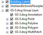
In an edit session (I am editing AshlandSchoolsFloorplan)
I then turn off all but the polyline layer.
I select all of the polyline layer.
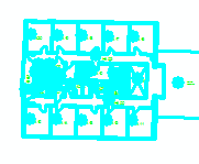
I hit Ctrl + c then Ctrl + v
I ensure that I am copying to the right layer
Turn off your cad drawing to make sure that the layer copied correctly.
I then will add all building labels from the annotation to the building_labels feature class.
If you need the polygon layer then repeat the steps above on with the Polyline turned off and the Polygon turned on.
I then will remove all cad drawings from the mxd
I then share as service.
- Mark as New
- Bookmark
- Subscribe
- Mute
- Subscribe to RSS Feed
- Permalink
It is not exactly in the spirit of the question as you asked it, but another potential alternative could be the CAD2Shp software solution. They have got a not obligation trial available for download that might suite your needs CAD2Shape: Convert AutoCAD DWG / DXF to ESRI Shape (.shp)
- Mark as New
- Bookmark
- Subscribe
- Mute
- Subscribe to RSS Feed
- Permalink
I'll second that. I've found CAD2Shape to be very useful in converting CAD. Of the several workflows available to convert CAD, CAD2Shape has been the most effective for me.
Chris Donohue, GISP