- Home
- :
- All Communities
- :
- Products
- :
- Data Management
- :
- Data Management Questions
- :
- CAD to GIS
- Subscribe to RSS Feed
- Mark Topic as New
- Mark Topic as Read
- Float this Topic for Current User
- Bookmark
- Subscribe
- Mute
- Printer Friendly Page
- Mark as New
- Bookmark
- Subscribe
- Mute
- Subscribe to RSS Feed
- Permalink
I am importing CAD files (stores plans) dwf/dwg into our ArcGIS system. Everything seems fine on that front except that I would like it to come in at the actual size of the store. In AutoCAD we do not have any geo referencing to the file however I would think with it being drawn to scale that I should at least be able to bring it in at that same scale just not the right place in the world. When I bring these files in they come in much larger than scale. Any trick or tips on how to do that. I would rather not do any manual adjusting.
Thanks,
Michael
Solved! Go to Solution.
Accepted Solutions
- Mark as New
- Bookmark
- Subscribe
- Mute
- Subscribe to RSS Feed
- Permalink
When I import cad I only use the annotation and line (you may need a polygon feature class)
I have two layers set up: the building_labels for the annotation (i have to import manually)
and they AshlandSchoolsFloorplan layer
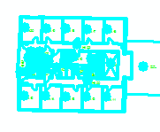
I position my cad drawing (GS-3.dwg) to a location
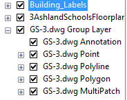
In an edit session (I am editing AshlandSchoolsFloorplan)
I then turn off all but the polyline layer.
I select all of the polyline layer.
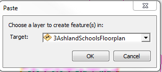
I hit Ctrl + c then Ctrl + v
I ensure that I am copying to the right layer
Turn off your cad drawing to make sure that the layer copied correctly.
I then will add all building labels from the annotation to the building_labels feature class.
If you need the polygon layer then repeat the steps above on with the Polyline turned off and the Polygon turned on.
I then will remove all cad drawings from the mxd
I then share as service.
- Mark as New
- Bookmark
- Subscribe
- Mute
- Subscribe to RSS Feed
- Permalink
You have to do some manual work, it shouldn't take you long tho. You need to set control points for your CAD dataset in Arc using georeferencing toolbar. You can read more about it in the links below.
- Mark as New
- Bookmark
- Subscribe
- Mute
- Subscribe to RSS Feed
- Permalink
To have it show up at the correct scale, one would have to lay it out in CAD in the same coordinate system as is being used in your mxd Data Frame properties. Most CAD drawings, however, are not done in coordinate systems that are commonly used in GIS. Furthermore, another complication is that most CAD is in a "flat world" - i.e. outside of their specific GIS add-ons they typically will not account for the curvature of the earth.
The practical implications of this is that even if the CAD file is laid out in the same coordinate system, if your store is large, the corners may seen a bit misaligned compared to what you would expect. I see this often with Developments - an engineering firm will send in a CAD file containing infrastructure plans and it will not cleanly mesh with the existing data in GIS. So typically it will still need spatial adjustment.
Chris Donohue, GISP
- Mark as New
- Bookmark
- Subscribe
- Mute
- Subscribe to RSS Feed
- Permalink
The way I deal with sizing issues for CAD files is, bring it in, then I geofeference the file using the Geofeferencing toolbar.

- Mark as New
- Bookmark
- Subscribe
- Mute
- Subscribe to RSS Feed
- Permalink
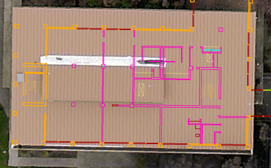
Thanks for all of the replies. My application that I have been tasked with is kind of different. My goal is to bring my dwg files into ArcGIS and serve them up to ArcGIS Server. Then I want to use some drawing tools that will measure the area. More of a markup form. In order to get the area though I need it be have the CAD file at the right size so when I draw the box it gets the right area.
I'm not worried where in the world they are at this point. Currently mine are going to 0,0 which is fine cause I can always zoom to that spot but I would like for them to come in at the correct size.
A rough example
- Mark as New
- Bookmark
- Subscribe
- Mute
- Subscribe to RSS Feed
- Permalink
What you could do is draw a line with the exact length of the project or the side of a building. Then use the georeferencing tools to match that line to the corresponding dwg. That way you know that the drawing is has the right lengths.
- Mark as New
- Bookmark
- Subscribe
- Mute
- Subscribe to RSS Feed
- Permalink
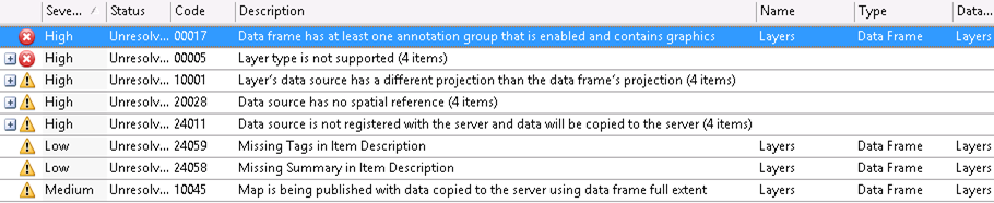
So I found this toolbar but it doesn't allow me to use it on a layer that was brought in using the arctoolbox "CAD to Geodatabase". I can use it if I just use the Add data button to bring it in but then when I go to share it as a service it I get a bunch of errors. Why is nothing easy?
- Mark as New
- Bookmark
- Subscribe
- Mute
- Subscribe to RSS Feed
- Permalink
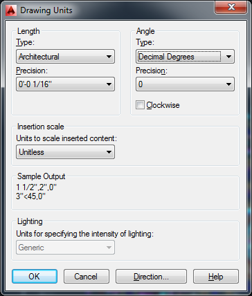
Use the units command and find the units of each drawing. this to find the percent that you will need to enlarge each, based on the CS environment you are going into - likely meters or feet from the likely CAD default inches for architectual. If possition doesn't matter, just scale the DWG/DWF by the percentage amount you figured out into a blank drawing where you have set units to the same as your GIS environment. If some of your drawing are unitless, as they are many times, you can just change the unit to match your GIS environment and scaling should then become auto while bringing it in. This does sound like a units issue. There are several methods to bringing DWGs into blank DWGs that have proper settings set up. The now, old fashion xrefing method allows for scaling while bringing it in.
- Mark as New
- Bookmark
- Subscribe
- Mute
- Subscribe to RSS Feed
- Permalink
I'm not much of an autocad person but when I type in unites into the command line for autocad this is what I get back. How do I proceed from here?
- Mark as New
- Bookmark
- Subscribe
- Mute
- Subscribe to RSS Feed
- Permalink
So it looks like when I measure the length of my building in CAD it is 418 feet and when I measure it after bringing it in GIS it is 16493. So very close to 40 (39.46) times larger in GIS then in CAD. I did the same with the length and got 348 to 13676 (39.3). Not sure this helps much but as I find out things I think are clues I thought I would share in hopes somebody can help me with this task.