- Home
- :
- All Communities
- :
- User Groups
- :
- CAD/GIS Data Integration
- :
- Questions
- :
- Re: Contours at incorrect size and position in Aut...
- Subscribe to RSS Feed
- Mark Topic as New
- Mark Topic as Read
- Float this Topic for Current User
- Bookmark
- Subscribe
- Mute
- Printer Friendly Page
Contours at incorrect size and position in AutoCAD LT .dwg. [ArcGIS Pro convert to CAD)
- Mark as New
- Bookmark
- Subscribe
- Mute
- Subscribe to RSS Feed
- Permalink
- Report Inappropriate Content
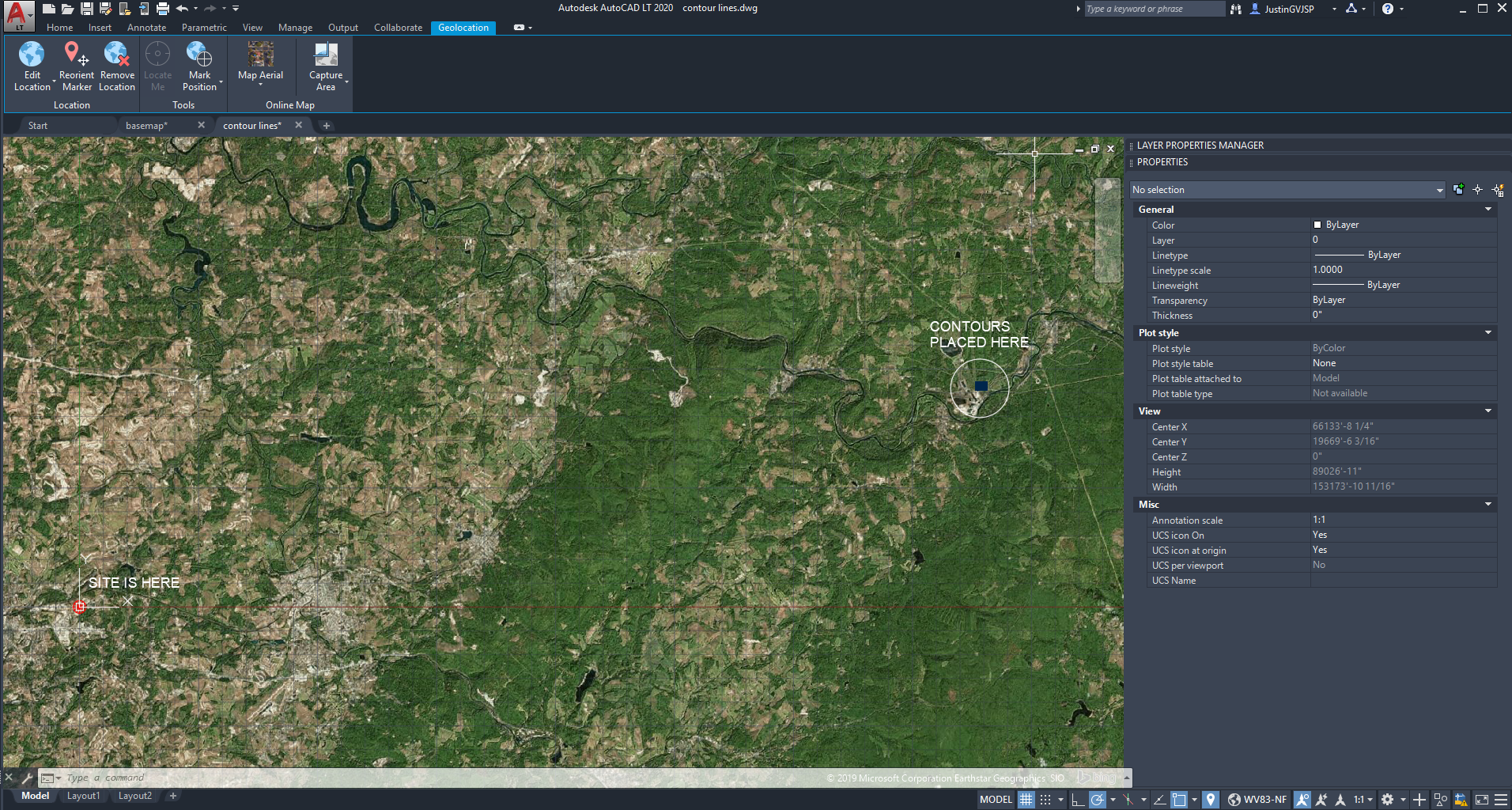
Attempting workflow to pull contours from ArcGIS Pro and open them as working files in AutoCAD LT. After I convert the contours in ArcGIS Pro to a CAD file, AutoCAD LT opens the file, but incorrectly aligned with the AutoCAD basemap. The scale of the contours is also too small - appears to be at a scale factor of 1/12.
My steps are as follows:
1.) Set Up AutoCAD LT Drawing as new, acadlt.dwt template, with units: architectural, inches. I've also tried feet. Geo > set location from map > address > GIS Coordinate System > Drawing Unit: Inches > place at (0,0) ; 90deg North. Save File, basemap.dwg
2.) In ArcGIS Pro: Export contour lines w/ "Export to CAD" Tool;

Unit: US-SurveyFT, Output Type - DWG version 2018; Ignore Paths in Tables, Seed File: basemap.dwg; Match Output Coordinate System, Save File: contour lines.dwg
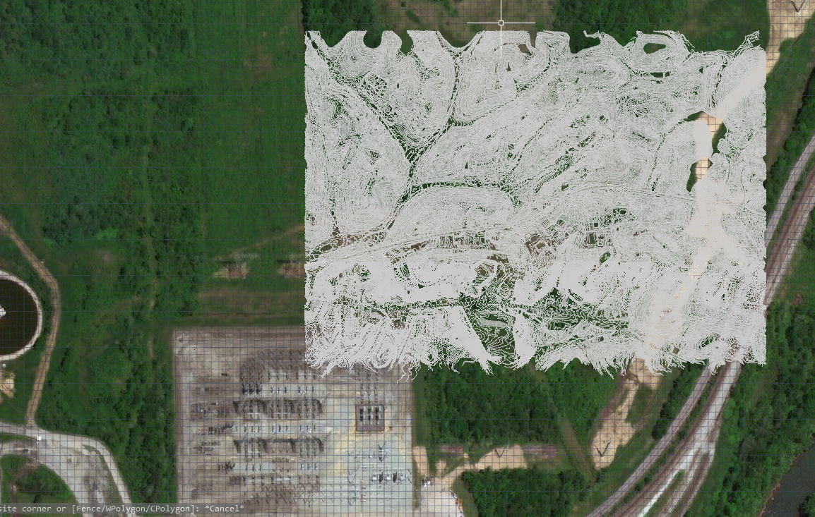
3.) In AutoCAD LT: Open contour lines.dwg > contours are too small, improperly located, and not aligned with anything on the basemap.
- Mark as New
- Bookmark
- Subscribe
- Mute
- Subscribe to RSS Feed
- Permalink
- Report Inappropriate Content
It looks to me like this might be a coordinate system issue. Have you tried changing the coordinate system and see where the CAD file ended up?
What I normally do is, open up ArcGIS, assign the coordinate system that I think is correct to my map, then load the CAD data. I then see if the data lines up to the basemap. If not, I play around with my coordinate system to make it work.
- Mark as New
- Bookmark
- Subscribe
- Mute
- Subscribe to RSS Feed
- Permalink
- Report Inappropriate Content
This question involves two issues: 1) “Contours too small” 2) "improperly located"
Solution for issue 1): the linear unit is incorrect –you are using inches as drawing unit, we recommend you to check the linear unit for your contour line, and change it to feet, if necessary. Then, the scale of the contour will be fixed.
2) issue 2 is tie to the the way AutoCAD handles maps. AutoCAD makes the maps origin point to a point in the AutoCAD drawing. You will need choose a center point that is the same as the origin of the coordinate system.
For example, when AutoCAD asks you for "point for the location", you put the real coordinates of the location. Go to ArcGIS Pro, and check the real coordinate. See video
- Mark as New
- Bookmark
- Subscribe
- Mute
- Subscribe to RSS Feed
- Permalink
- Report Inappropriate Content
Hi Cici, thanks for your response. I'm not able to see the video you've posted at this time - it is still "currently encoding."
I tried different iterations of the advice you provided, placing the contour at "real" coordinates for the location, but was still running into the same issue. It's possible I misunderstood your advice - do you have another way I could view the video or could you clarify the steps provided above?
I'm starting to think this may be a limitation with AutoCAD LT, or either way it's a very confusing integration process.
Thank you again - this has been a head scratcher for me!
- Mark as New
- Bookmark
- Subscribe
- Mute
- Subscribe to RSS Feed
- Permalink
- Report Inappropriate Content
The point you set for the red pin can't be random. You will need to select a point which you know what the real coordinate is on ArcGIS pro.
For example, in ArcGIS pro, I hover my mouse on the tip of the island (marked by red arrow) and got the coordinates.
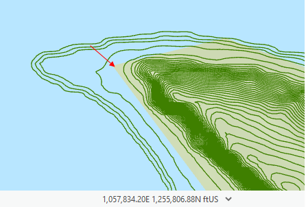
Then in AutoCAD, I placed the red pin on the tip of the island.
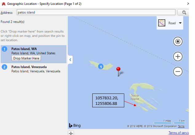
Choose the correct coordinate system, check "reference" and "unit". Change the drawing unit to feet, if necessary. Now I manually modify the coordinate of the "point for location" into the real coordinates of the red pin, which is
1057832.20, 1255806.88.
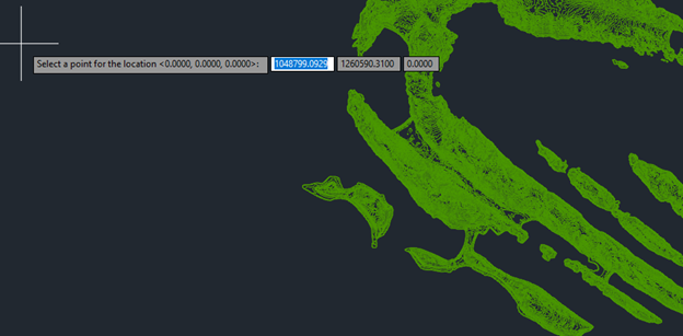
Done!