- Home
- :
- All Communities
- :
- Products
- :
- ArcGIS CityEngine
- :
- ArcGIS CityEngine Questions
- :
- Wire Frames wont turn off
- Subscribe to RSS Feed
- Mark Topic as New
- Mark Topic as Read
- Float this Topic for Current User
- Bookmark
- Subscribe
- Mute
- Printer Friendly Page
- Mark as New
- Bookmark
- Subscribe
- Mute
- Subscribe to RSS Feed
- Permalink
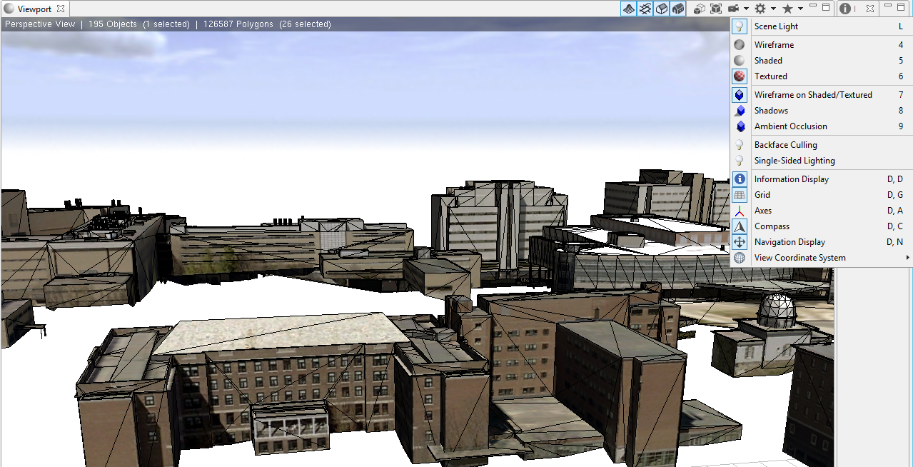
I have a Multipatch model that an outside firm created for CityEngine of our Campus Buildings.
For some reason there is a "wireframe" on the buildings in CityEngine that I cant turn off. It does not show in ArcScene even when I select the object (I was thinking maybe it was part of the geometry.)
I need to turn them off because they are horribly ugly.
In the attached image of one of the buildings the only view setting that is one is texture. If these lines are part of the texture why dont they show in ArcScene?
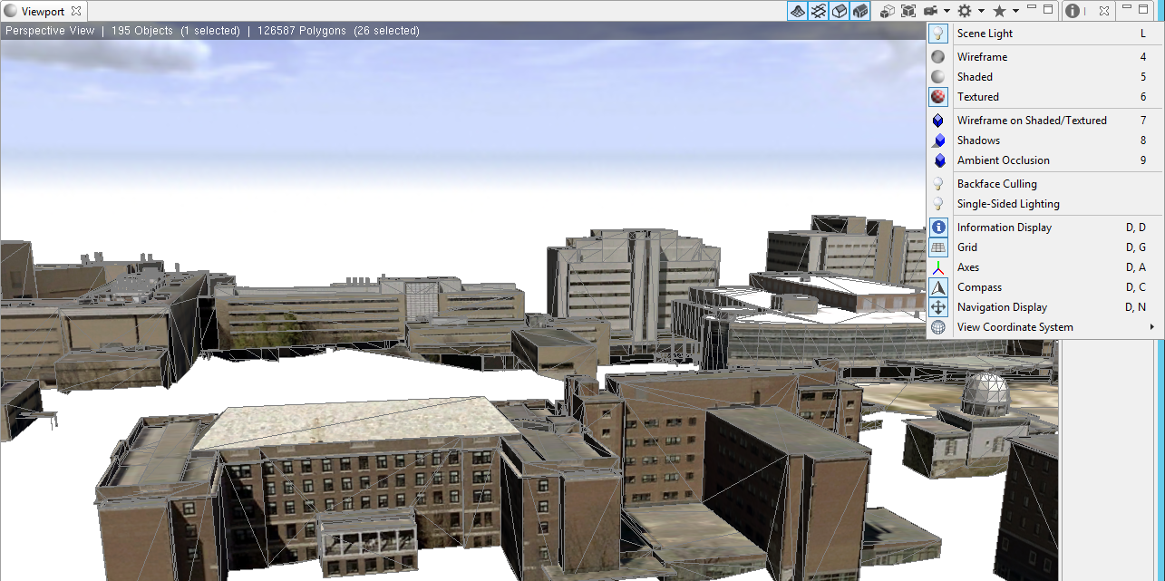
If I turn the wireframes on the texture on the lines that im calling the "wireframe" appear to become the true wireframe and are shown in black instead of grey.
Further more I cant import any multipatches into CE 2015.0, spoke to ESRI already and the ticket is still open.
Solved! Go to Solution.
- Mark as New
- Bookmark
- Subscribe
- Mute
- Subscribe to RSS Feed
- Permalink
Got it. I think the rule application might be the best solution then. It might be any rule application would have a similar effect.
What happens when you apply another shell rule generally? If you have any to test it.
- Mark as New
- Bookmark
- Subscribe
- Mute
- Subscribe to RSS Feed
- Permalink
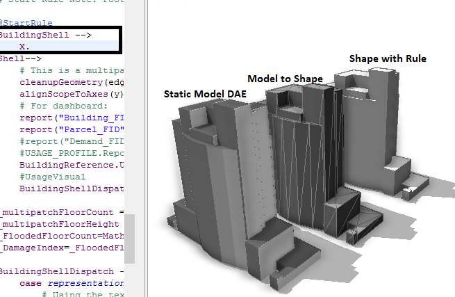
Shapes display with those lines. Models don't. And rules convert Shapes to models.
I have no idea what types of objects Shapes or Models are internally so I wouldn't apply the concept of casting here.
I haven't done OOP in years, so I really don't remember much about casting. Search the terms implements, interface, and casting, and you'll find details of that.
- Mark as New
- Bookmark
- Subscribe
- Mute
- Subscribe to RSS Feed
- Permalink
I guess what is confusing me is that I thought when imported they start as static models, and as part of the process you converted them to shapes, then applied a rule to make a rule based model in CE.
I was just using the word casting trying to understand if you were molding one type of object into another with a rule application. It sounds like any rule would work for this purpose. I did some experimentation and came up with this image. The raw DAE model does not have the lines (static model), converted to shapes does, but when the rule is applied and sent to X. it also does not have the lines but also is a little different (likely just a result of certain shapes being sent to white blank leafs). It the three combinations that is a little confusing.
Thanks for the help Chris! It makes a little more sense now.
- « Previous
-
- 1
- 2
- Next »
- « Previous
-
- 1
- 2
- Next »