- Home
- :
- All Communities
- :
- Products
- :
- ArcGIS CityEngine
- :
- ArcGIS CityEngine Questions
- :
- Why do the buildings I created through CGA scripts...
- Subscribe to RSS Feed
- Mark Topic as New
- Mark Topic as Read
- Float this Topic for Current User
- Bookmark
- Subscribe
- Mute
- Printer Friendly Page
Why do the buildings I created through CGA scripts different then manually created shapes?
- Mark as New
- Bookmark
- Subscribe
- Mute
- Subscribe to RSS Feed
- Permalink
- Report Inappropriate Content
I was working on learning how to tackle "stepped" building shapes when I ran across the difference in the make-up of building shapes created from a CGA script (or one of the "Building-from-Footprint" scripts and the buildings that I created manually. The script generated buildings seem to be created from the "bottom-up" while the manually created shapes are "top down" I've included an example of the two methods side-by-side.In the "Building-from-Footprint" method it's like I'm building the building shapes upside down. This has all kinds of ramifications.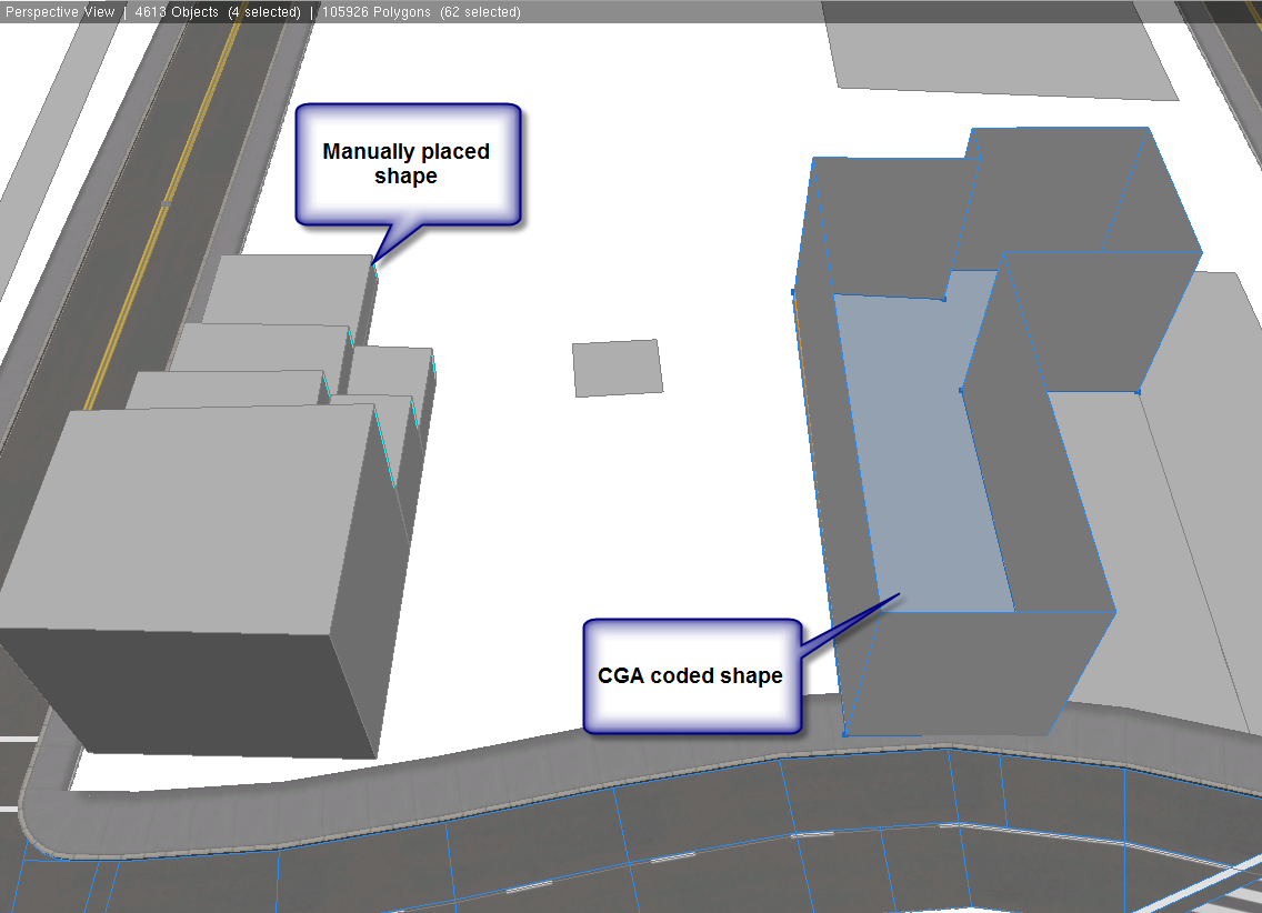
- Mark as New
- Bookmark
- Subscribe
- Mute
- Subscribe to RSS Feed
- Permalink
- Report Inappropriate Content
Hi Robert,
Going to take a shot in the dark, because I am not sure I understand the question. From first glance it looks like you did not comp(f) the top of the footprint, or perhaps orientation in your comp got changed.
Can we see the script in question?
David
- Mark as New
- Bookmark
- Subscribe
- Mute
- Subscribe to RSS Feed
- Permalink
- Report Inappropriate Content
Here is the script.
It's generally the "Building from Footprint" CGA script that is included in the ESRI.lib.
I deleted the " top : Roof " part of the comp(f) so you could see the inside of the shape.
***************************************************************************
***************************************************************************
version "2014.0"
const dirt_tex = "assets/3D_City_Design_Assets/Material_Library/DirtMap/Dirt Map 1.jpg"
attr groundfloor_height = 10
attr OverwriteColor = "#ffffff"
import Roof_Textures:"/ESRI.lib/rules/Roofs/Roof_Textures.cga"
attr wallTexture = "assets/3D_City_Design_Assets/Material_Library/WallTextures/wall_concrete_4.jpg"
attr wallTexture2 = "assets/3D_City_Design_Assets/Material_Library/WallTextures/Brick Red No Mortar Running Bond.jpg"
//import facade : "Facade_StClairWestside5.cga"
@Hidden
attr originalScopeY = 0
@StartRule
SlantedBuildingFootprint -->
# Align scope to have y axis up.
alignScopeToAxes(y)
# Save this shape's height.
set(originalScopeY, scope.sy)
# Flatten footprint by scaling y to zero.
s('1,0,'1)
// extrude(originalScopeY)
// color(1,0,0)
# Make it transparent for demo purpose.
//set(material.opacity, 0.5)
# At this point the top or bottom can be used for floors (basement and upper floors.
# For use on non-flat building footprint,
# so project footprint to terrain using Align Shapes to Terrain (Project All option).
//Building -->
extrude (10)
comp(f) {front : Facade | side : Side }
#! SIZE 30.0 27.26128
@Location(1218,496)
Facade -->
setupProjection(0, scope.xy, 1.5, 1, 1)
setupProjection(2, scope.xy, '1, '1)
facade.Facade
Side -->
facade.Facade
Roof -->
Roof_Textures.Generate
*************************************************************************************
- Mark as New
- Bookmark
- Subscribe
- Mute
- Subscribe to RSS Feed
- Permalink
- Report Inappropriate Content
Hi Robert,
Nope. You lost me.
CGA will always start geometry creation process relative to the base shape, thus if the shape is on the ground, it will be a bottom up process because it is building it from the base shape.
What is it you want to achieve with CGA that you are doing now with manually orienting and modeling shapes? What needs to change for you to accomplish your goals?
- Mark as New
- Bookmark
- Subscribe
- Mute
- Subscribe to RSS Feed
- Permalink
- Report Inappropriate Content
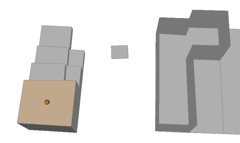
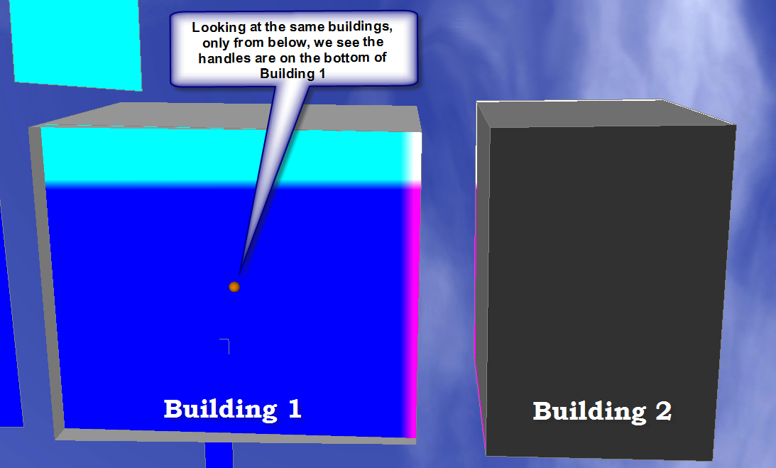
Maybe this will help me explain:
The manually built shape has the handles, the shape is built from the "bottom up". What you would normally see if you extrude a building shape.
Example 1
Example 2 we're looking at the same two shapes only from below the y-axis (or underneath). Here we see the handle is showing that the shape on the right is upside down.
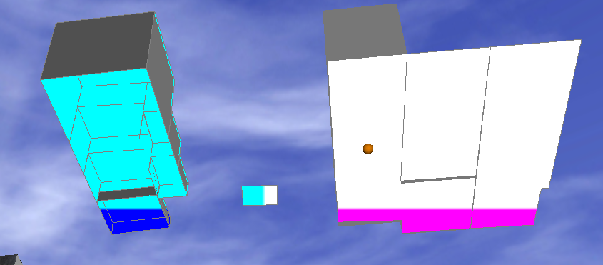
Does that make it clearer?
- Mark as New
- Bookmark
- Subscribe
- Mute
- Subscribe to RSS Feed
- Permalink
- Report Inappropriate Content
Hi Robert,
So to clarify you are trying to represent setbacks for buildings procedurally?
Similar to this image?
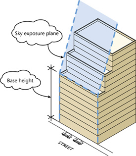
David
- Mark as New
- Bookmark
- Subscribe
- Mute
- Subscribe to RSS Feed
- Permalink
- Report Inappropriate Content
No, I'm trying to understand how the shapes are constructed. Let me go to something less complex, the building shapes aren't really that important.
Here is a simpler example:

The shapes are constructed in completely different ways.
If I use the handles from Building 1, the extrusion for Building 1 will go in the opposite direction of Building 2.
- Mark as New
- Bookmark
- Subscribe
- Mute
- Subscribe to RSS Feed
- Permalink
- Report Inappropriate Content
The handle on the bottom you're picking up is the original shape (building footprint). CGA doesn't change the original shape it simply builds on top of it, using it as a seed. Use the toggle shapes button and it will disappear (F11).
Theres a tool to "Convert Models to Shapes" if you wish to modify your CGA models using handles.
- Mark as New
- Bookmark
- Subscribe
- Mute
- Subscribe to RSS Feed
- Permalink
- Report Inappropriate Content
I think I'm getting stuck on the difference between a model and a shape. When I manually extrude a building shape, the shape is changed to whatever I make it. Using the CGA scripts, the extruded "shape" is actually a MODEL. If I toggle the Model on/off, the CGA created buildings turn on and off. , This means when I create a building using the CGA method on my building "walls" they are Model structures not shapes.
The "Building from Footprint" creates models.
- Mark as New
- Bookmark
- Subscribe
- Mute
- Subscribe to RSS Feed
- Permalink
- Report Inappropriate Content
Hi, I wonder why does the vertice numbers increase in shape building2? I created a rectangular shape. It has 4 vertices and I note them coordinate. And when I extruded this shape by using CGA rule, it occured 24 vertices and first coordinate of 4 vertices is a little bit different. I extrude this shape by handle (by using 'rectangular shape creation' tool) it has 8 vertice and first 4 vertice is not different so its coordinate true for me.